 In this chapter, I will
finish the outside of the fuselage that includes the NACA scoop, hard points for
the landing gear door, routing the bottom corners, building in the NAV antenna,
carving out the fuel sight gauges and glassing the outside skin.
In this chapter, I will
finish the outside of the fuselage that includes the NACA scoop, hard points for
the landing gear door, routing the bottom corners, building in the NAV antenna,
carving out the fuel sight gauges and glassing the outside skin.| What's up? |
| In this chapter, I will
finish the outside of the fuselage that includes the NACA scoop, hard points for
the landing gear door, routing the bottom corners, building in the NAV antenna,
carving out the fuel sight gauges and glassing the outside skin. |
| Building the NACA Scoop |
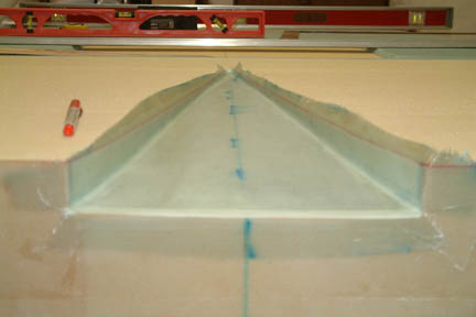
 This is
the part that is built onto the bottom of the fuselage and is shaped to scoop up air for
cooling the engine in-flight. As always, I used my laser to mark the centerline
along the entire length of the fuselage bottom. I then traced out the NACA scoop
location onto the bottom of the fuselage. This is
the part that is built onto the bottom of the fuselage and is shaped to scoop up air for
cooling the engine in-flight. As always, I used my laser to mark the centerline
along the entire length of the fuselage bottom. I then traced out the NACA scoop
location onto the bottom of the fuselage.
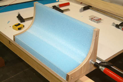
The next step is to build up the scoop structure using a combination of 2" and 1" urethane foam blocks. This kind of foam is extremely soft - it'll fall apart if you stare at it long enough... but it is easy to shape. I traced and cut up the foam carefully using the paper template (left). I then micro-ed the foam down onto the fuselage bottom. Since the fuselage bottom is curved, unlike the foam, which is flat, I needed to clamp the foam down such that it conforms to the fuselage contour during cure. I had a lot of difficulty in holding the 2" foam to conform, especially along the inside edges of the foam block. Anxious to keep them in place without gaps, I used extra weights, big clamps and shims... Sounds like trouble brewing? It was!
After
cure, I removed all the weights & clamps and did my inspection. The foam
blocks attached fine to the fuselage as expected. However, my aggressive clamping,
created some deformation on the fuselage bottom. It formed a gradual
'V' shape depression along the center of the NACA scoop location with the worst
'bump' of 3/8" deep - 10" from the forward bulkhead |
 I
pondered over it for a few days and asked for advice on the Cozy Web site. I
finally decided to remove the foam and do it over. That was a considerable setback. To remove the foam, I took a
spackle spatula and a leather hammer and
chiseled the 2" & 1" foam off (above the micro). It was easier than
expected, I removed all the foam in 30 minutes. As for the micro, it was a
different story. I resorted to a combination of belt sander, palm sander and
sanding stick to get them off. It took me 4.5 hours. I just can't wait until the
real sanding task arrives I
pondered over it for a few days and asked for advice on the Cozy Web site. I
finally decided to remove the foam and do it over. That was a considerable setback. To remove the foam, I took a
spackle spatula and a leather hammer and
chiseled the 2" & 1" foam off (above the micro). It was easier than
expected, I removed all the foam in 30 minutes. As for the micro, it was a
different story. I resorted to a combination of belt sander, palm sander and
sanding stick to get them off. It took me 4.5 hours. I just can't wait until the
real sanding task arrives |
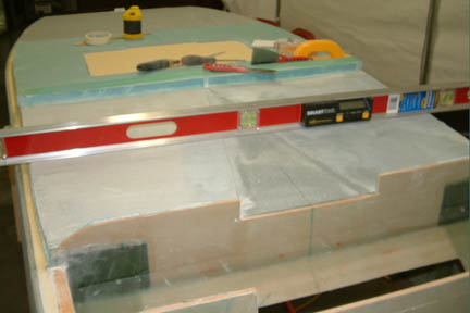
 I
was a bit more careful the second time around. I propped up the fuselage bottom and
made sure it was level with my digital level. I then crawled under the fuselage with a
straight edge and made sure the fuselage bottom was perfectly flat. Sound
paranoid? Not really... just don't think I'd be in the mood for 'third time is
a charm' bit I
was a bit more careful the second time around. I propped up the fuselage bottom and
made sure it was level with my digital level. I then crawled under the fuselage with a
straight edge and made sure the fuselage bottom was perfectly flat. Sound
paranoid? Not really... just don't think I'd be in the mood for 'third time is
a charm' bit |
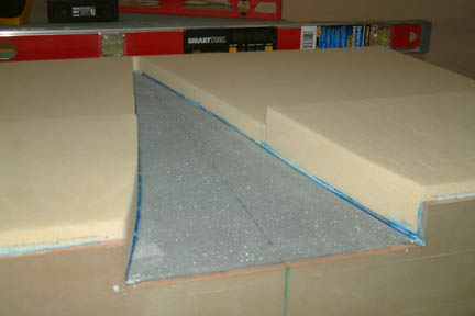
 I
also noted a few comments from other builders that the foam dimensions per plan
were not quite long enough to provide a continuous flat surface to the bottom of the
fuselage. If you put a straight edge from the landing brake to the forward LG
bulkhead, you will find a dip as much as 3/4". Some builders decided to
fill it with micro
while others added additional foam. I chose the latter approach. I
also noted a few comments from other builders that the foam dimensions per plan
were not quite long enough to provide a continuous flat surface to the bottom of the
fuselage. If you put a straight edge from the landing brake to the forward LG
bulkhead, you will find a dip as much as 3/4". Some builders decided to
fill it with micro
while others added additional foam. I chose the latter approach. |
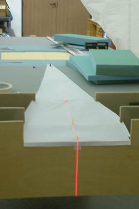
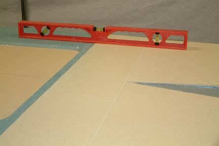 I
took my line laser and projected a flat line along the surface of the fuselage
bottom. It helped me to locate the starting point of the fuselage curvature. It
turned out to be a couple inches from the landing brake. I ended up
extending an additional 7" of foam to the fuselage bottom. After
all the sanding was done, you can see there is no gap underneath the straight
edge. I like it much better this way. I
took my line laser and projected a flat line along the surface of the fuselage
bottom. It helped me to locate the starting point of the fuselage curvature. It
turned out to be a couple inches from the landing brake. I ended up
extending an additional 7" of foam to the fuselage bottom. After
all the sanding was done, you can see there is no gap underneath the straight
edge. I like it much better this way. |
| Parts A, B, C & D |
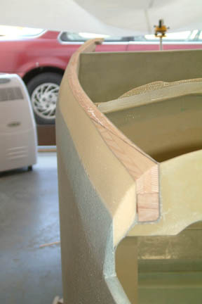
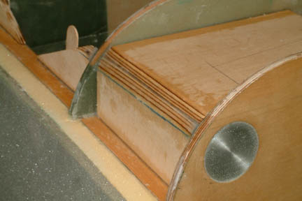 These
small wooden parts were made to support additional foam blocks along the sides
of the fuselage. It took me a lot more time than expected to fiddle around with
it and fit it in place. Some took me 3 tries to get it right - especially parts C
& D. I finally gave up and filled the gap with flox. Notice the round (instead
of square) engine mount anchors that sit just below part D. These
small wooden parts were made to support additional foam blocks along the sides
of the fuselage. It took me a lot more time than expected to fiddle around with
it and fit it in place. Some took me 3 tries to get it right - especially parts C
& D. I finally gave up and filled the gap with flox. Notice the round (instead
of square) engine mount anchors that sit just below part D. |
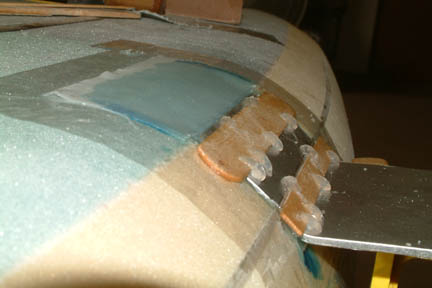
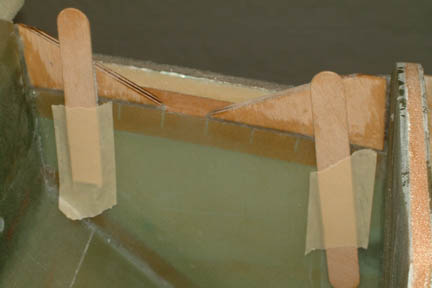 Instead
of using nails to hold the wood parts in place during cure, I taped a couple stir
sticks to the fuselage walls as support. This worked well and I do not have to
fill the nail holes later. If you look close, you can see I had a piece of duct
tape on the face of the stir stick - to keep it from sticking to the flox. I
also lined up parts A, B & C flush with the fiberglass surface and not
the edge of the longeron. Instead
of using nails to hold the wood parts in place during cure, I taped a couple stir
sticks to the fuselage walls as support. This worked well and I do not have to
fill the nail holes later. If you look close, you can see I had a piece of duct
tape on the face of the stir stick - to keep it from sticking to the flox. I
also lined up parts A, B & C flush with the fiberglass surface and not
the edge of the longeron. |
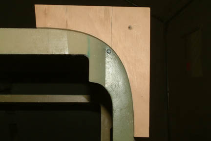
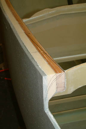
| To joggle or not to joggle? |
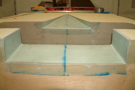
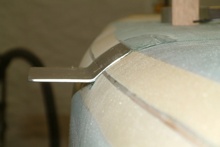
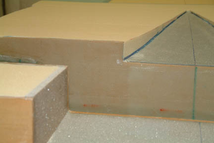 The
next step requires a joggle to be carved along the foam edge of the NACA scoop
and along the aft face of the aft LG bulkhead. This joggle is to accommodate a
landing gear cover (to be built in Chapter 9). This will be difficult for those
to visualize without a drawing on hand. All builders dread this step - myself
included. I searched through the archives and posted a question on the Cozy forum.
Wayne Hick's web site offered an alternative method for attaching the landing
gear cover. I liked his approach better not because it is less work, but it allows
me to make a higher quality part. Therefore, as shown (left) no joggle! I'll say
I am committed at this point. Since the landing gear cover will not be made
until Chapter 9, you just have to wait till then. If you want to know how I'll
go about it, you need to visit Wayne Hicks' site for now. The
next step requires a joggle to be carved along the foam edge of the NACA scoop
and along the aft face of the aft LG bulkhead. This joggle is to accommodate a
landing gear cover (to be built in Chapter 9). This will be difficult for those
to visualize without a drawing on hand. All builders dread this step - myself
included. I searched through the archives and posted a question on the Cozy forum.
Wayne Hick's web site offered an alternative method for attaching the landing
gear cover. I liked his approach better not because it is less work, but it allows
me to make a higher quality part. Therefore, as shown (left) no joggle! I'll say
I am committed at this point. Since the landing gear cover will not be made
until Chapter 9, you just have to wait till then. If you want to know how I'll
go about it, you need to visit Wayne Hicks' site for now. |
| Glassing the NACA Scoop |
 Glassing
the NACA scoop requires normal procedure. I rounded off all edges and tight
corners with micro before glassing. It was a bit challenging toward the front
tip of the NACA scoop because there is not much height to the foam. I cut up a credit card and made a
plastic strip with one of its corners at the tip of the strip. It worked well to
get the micro into tight corners. I also filled the protruded 1/8" PVC foam
lip (at the lower end of the scoop) with micro such that the glass will lay down
smoothly (remember, I am not doing the joggle). Glassing
the NACA scoop requires normal procedure. I rounded off all edges and tight
corners with micro before glassing. It was a bit challenging toward the front
tip of the NACA scoop because there is not much height to the foam. I cut up a credit card and made a
plastic strip with one of its corners at the tip of the strip. It worked well to
get the micro into tight corners. I also filled the protruded 1/8" PVC foam
lip (at the lower end of the scoop) with micro such that the glass will lay down
smoothly (remember, I am not doing the joggle). |
 After
the glass is cured, I put duct tape on the foam along the back side of the
glass and drew a line (red) along the back side of the glass such that I can see
where the top of the foam meets the glass. With the FEIN cutter, I trimmed off
the excess glass. Using my sanding stick, I carefully smoothed out the
edges. You can see I got markings all over the place, but they will be covered
up when the plane gets painted eventually. After
the glass is cured, I put duct tape on the foam along the back side of the
glass and drew a line (red) along the back side of the glass such that I can see
where the top of the foam meets the glass. With the FEIN cutter, I trimmed off
the excess glass. Using my sanding stick, I carefully smoothed out the
edges. You can see I got markings all over the place, but they will be covered
up when the plane gets painted eventually. |
| Sanding Fuselage Aft End |
 There were conflicting
interpretations plus there were new clarifications from Nat per news letter #78 which
dictates that all foam be removed outboard of the top longerons and LWYs to
provide for glass-to-wood bonds in the spar box area. There were conflicting
interpretations plus there were new clarifications from Nat per news letter #78 which
dictates that all foam be removed outboard of the top longerons and LWYs to
provide for glass-to-wood bonds in the spar box area.
First I addressed Nat's clarifications - removing the foam from the top longerons and LWY was easy. I pre-marked the foam locations, removed them with a chisel, then sanded a 1.5" slope to the edges all around the opening.
[Hindsight] I am now in Chapter 21 - joining the top and bottom skins of the strakes. This 1.5" slope turned out to be an indentation that I need to fill at this time. This 1.5" slope should only apply to locations where the foam meets the wood. The vertical section of the opening - that is not adjacent to the wood should not be sloped.
The next step is to sand the fuselage back sides. I was a bit confused by the instructions and looked through the archives. There's a slight conflict in interpretation between Cozy Builder site Q&A for Chapter 7 and one of the e-mail clarifications from Nat.
Per Nat's e-mail, the tapering should be as follows: "Imagine a line approx. 25" forward from the firewall perpendicular to the upper longeron, gradually taper the sides from this line back to the firewall".
Per Cozy Builder site Q&A Chapter 7, "Visualize a hot wire cutter, one side fastened on a pivot 25" forward of the firewall...." |
 I
went ahead and started sanding between the 2 guidelines and hoped for the best. I
used a straight sanding block and tried to connect the 25" position to the
firewall. Here's what I got... I
went ahead and started sanding between the 2 guidelines and hoped for the best. I
used a straight sanding block and tried to connect the 25" position to the
firewall. Here's what I got... |
 However,
too much of a straight line sanding will expose the electrical channel
underneath. Fortunately, this will be covered up later on. However,
too much of a straight line sanding will expose the electrical channel
underneath. Fortunately, this will be covered up later on. |
 I
was a bit more careful on the other side, though you can still see the
electrical channel just starting to show. I
was a bit more careful on the other side, though you can still see the
electrical channel just starting to show. |
 I
have a gap along the lower longerons (on both sides of the fuselage) as many
builders have. I filled them with micro and contoured later on before glassing. I
have a gap along the lower longerons (on both sides of the fuselage) as many
builders have. I filled them with micro and contoured later on before glassing. |
| Sanding Block For The Fuselage Bottom |
 The next
step is to round off the edges along the fuselage bottom all the way from the
front (F22) to the firewall. A template is provided in the drawing to show
the desirable curvature. Many builders, myself included, decided to use the
template and make a sanding block for shaping the fuselage edges. One of the
builders made a nice durable sanding block for this purpose, and this tool has been
passed around among the Cozy
builders when needed. Instead of chasing it down, I decided to make
my own. The next
step is to round off the edges along the fuselage bottom all the way from the
front (F22) to the firewall. A template is provided in the drawing to show
the desirable curvature. Many builders, myself included, decided to use the
template and make a sanding block for shaping the fuselage edges. One of the
builders made a nice durable sanding block for this purpose, and this tool has been
passed around among the Cozy
builders when needed. Instead of chasing it down, I decided to make
my own. |
 I
traced out the sanding block template (supplied by the drawings) on a 1/2" thick plywood board and made a set (2) of
them. It turned out that the curvature of the template matches exactly to the
rounded corners of the F22. I
traced out the sanding block template (supplied by the drawings) on a 1/2" thick plywood board and made a set (2) of
them. It turned out that the curvature of the template matches exactly to the
rounded corners of the F22. |
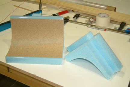
 I sandwiched a foam block between these two wood templates, and used a hot wire to carve out its curvature into the foam. This foam block forms the basis of my fuselage sanding block. The width of the block is about 16" wide. I had two concerns at this point: 1) The foam block may be too long to accommodate the curvature of the fuselage, and; 2) I will need two pieces of sand paper to cover the entire surface for the block, therefore leaving a seam between the sand papers. |
 I
decided to cut the sanding block into 2 shorter ones - 11" and 5" (the
standard length of a sand paper sheet is 11"). I also cut up a couple of
foam blocks and microed them onto the back of the sanding block as handles. If you
look closer, you can see I applied two strips of packing tape along the upper
and lower edges of the sanding block. The objective of the packing tape is to
prevent excessive foam to foam contact during sanding. I
decided to cut the sanding block into 2 shorter ones - 11" and 5" (the
standard length of a sand paper sheet is 11"). I also cut up a couple of
foam blocks and microed them onto the back of the sanding block as handles. If you
look closer, you can see I applied two strips of packing tape along the upper
and lower edges of the sanding block. The objective of the packing tape is to
prevent excessive foam to foam contact during sanding.
My initial plan was to glass the curved surface of the foam then spray glue the sand paper onto the cured glassed surface. I found out, accidentally, that double sided tape holds the sand paper directly onto the foam nicely. Therefore, I applied 5 strips of double sided tape on the back of the sand paper and slapped it onto the curvature of the sanding block. I like this approach better because the double sided tape does not add much thickness to the curvature and the sand paper can be removed quite easily for different grit as required.
It turned out that the shorter of the two sanding blocks (5" width) worked out much better than the wider one. Its because there is less friction and I can stay with the curvature better. |
| Mark The Sanding Path |
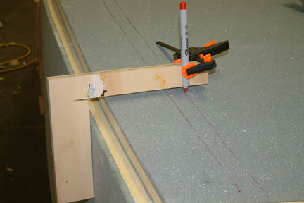 Before
trimming or sanding along the edges of the fuselage, I needed some form of marking
to guide my sanding path. I used a piece of 1/2" scrap board and cut a 90o
angle on it. I used this thicker board because it 'hugs' the fuselage sides better
and gives you a more consistent distance between the fuselage sides and the line
mark. Then I clamped a felt tip pen onto it at the desired position and traced the
path along the fuselage. Surprisingly, the clamp held the pen in place
well. Before
trimming or sanding along the edges of the fuselage, I needed some form of marking
to guide my sanding path. I used a piece of 1/2" scrap board and cut a 90o
angle on it. I used this thicker board because it 'hugs' the fuselage sides better
and gives you a more consistent distance between the fuselage sides and the line
mark. Then I clamped a felt tip pen onto it at the desired position and traced the
path along the fuselage. Surprisingly, the clamp held the pen in place
well. |
| The First Cut (45o Angle) |
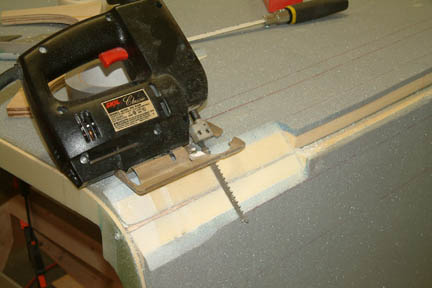 I
followed the instructions to the letter for my first cut - cut slowly and checked
every 1" along the way. In addition, I added a 'cut line' along the
fuselage as a guide. From the drawing, I calculated the distance of the 'cut
line' to the foam edge is 1.3". In other words, if I take a 45o
cut with my jig saw and cut along the 'cut line', I should get a .25" of
width on the lower longeron. I
followed the instructions to the letter for my first cut - cut slowly and checked
every 1" along the way. In addition, I added a 'cut line' along the
fuselage as a guide. From the drawing, I calculated the distance of the 'cut
line' to the foam edge is 1.3". In other words, if I take a 45o
cut with my jig saw and cut along the 'cut line', I should get a .25" of
width on the lower longeron.
I found a jig saw blade at Home Depot (Bosch) which is long enough for the angle cut. Therefore, no need to make a custom saw blade. The result looked pretty good. After the cut, I followed with a belt sander to make sure I got a nice .25" of the lower longer exposed - from the front (F22) to the mid/end of the landing brake. |
| Sanding The Right Fuselage Bottom |
 I did
not make the secondary cut per plan because I was concerned about making too
deep of a cut. Instead, I took a belt sander and ran along the full length of
the fuselage (lightly) using the exposed width of the longeron as a guide. I
have the 1/4" exposed longeron at F22 and eventually tapered to just the
edge of the longeron at the end of the landing brake. You can see the various
sanding tools I used I did
not make the secondary cut per plan because I was concerned about making too
deep of a cut. Instead, I took a belt sander and ran along the full length of
the fuselage (lightly) using the exposed width of the longeron as a guide. I
have the 1/4" exposed longeron at F22 and eventually tapered to just the
edge of the longeron at the end of the landing brake. You can see the various
sanding tools I used |
 To
smooth out the fuselage bottom, I cut across a 3" sanding belt for the
purpose. Instead of running the sanding belt side to side (as polishing your
shoes), I held the belt tight and slid it along the full length of the fuselage
bottom edge. It shapes the fuselage bottom edges nicely. Be careful with the stiff edge of the
belt, I got a couple of good gouges on the side of the fuselage to show. I later
found that a soft cloth type 3" sanding belt worked much better than the
stiff ones. Between the 5" sanding block, belt sander, and hand sander, I
managed to get a reasonable rounded edge along the fuselage
bottom. It fits the template reasonably well, but not perfectly. To
smooth out the fuselage bottom, I cut across a 3" sanding belt for the
purpose. Instead of running the sanding belt side to side (as polishing your
shoes), I held the belt tight and slid it along the full length of the fuselage
bottom edge. It shapes the fuselage bottom edges nicely. Be careful with the stiff edge of the
belt, I got a couple of good gouges on the side of the fuselage to show. I later
found that a soft cloth type 3" sanding belt worked much better than the
stiff ones. Between the 5" sanding block, belt sander, and hand sander, I
managed to get a reasonable rounded edge along the fuselage
bottom. It fits the template reasonably well, but not perfectly. |
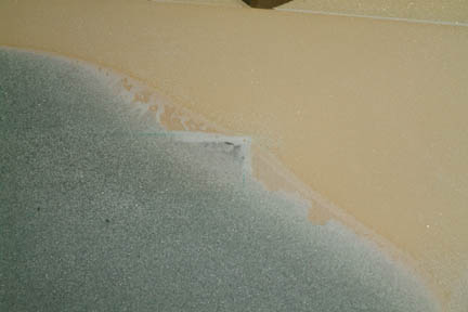
| Landing Brake Depression |
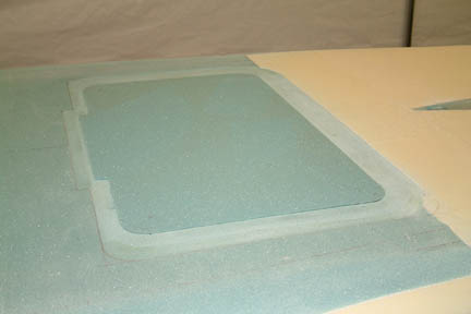 A
1/16" depression is required around the landing brake. Instead of sanding
in the depression by hand, I used the Dremel with the small grinding wheel set at
a 1/16" protrusion and routed out the depression. I rounded the corners and
hope it will work out fine. A
1/16" depression is required around the landing brake. Instead of sanding
in the depression by hand, I used the Dremel with the small grinding wheel set at
a 1/16" protrusion and routed out the depression. I rounded the corners and
hope it will work out fine.
The next step is to put a 1" wide duct tape around the landing brake. During my visit with Wayne Hicks, he demonstrated a quick and easy technique to rip out an 1" wide duct tape for this application. I tried it at home and just didn't like the rough edges and the occasional bumps on the surface of the multi-layered duct tape. I decided to go back to the double sided tapes. I hope I won't regret this! |
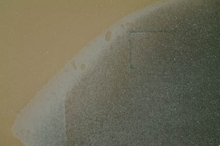
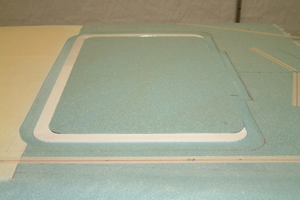 I
used 2 types of double sided foam tapes (as shown in the picture). The white one
is thinner than the green/white one and is about 1/32" thick. Between the
two layers of foam tape, they are flush with the landing brake. In addition, the
corners are easier to trim with a razor blade. Note that the outside edge of the
tape will define the outline of your landing brake. I
used 2 types of double sided foam tapes (as shown in the picture). The white one
is thinner than the green/white one and is about 1/32" thick. Between the
two layers of foam tape, they are flush with the landing brake. In addition, the
corners are easier to trim with a razor blade. Note that the outside edge of the
tape will define the outline of your landing brake. |
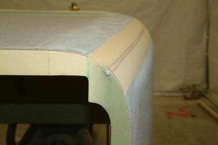
| 1/16" Front Joggle |
 A
1/16" joggle is also required along the front edge of the fuselage
including F22. This joggle is to accommodate the nose cone such that the
transition from the fuselage body is smooth. I pre-marked the 1/16" along
the front of the F22 and used a router to remove the fiberglass and foam, Though
the router is heavy, it allows a more steady cut than a Dremel. I also used duct tape along the inner edge of the fuselage. I finished the edges with
sanding paper and my special sanding sticks. Result looked pretty good! A
1/16" joggle is also required along the front edge of the fuselage
including F22. This joggle is to accommodate the nose cone such that the
transition from the fuselage body is smooth. I pre-marked the 1/16" along
the front of the F22 and used a router to remove the fiberglass and foam, Though
the router is heavy, it allows a more steady cut than a Dremel. I also used duct tape along the inner edge of the fuselage. I finished the edges with
sanding paper and my special sanding sticks. Result looked pretty good! |
| Foot Step (a slight deviation from plan) |
 The next
task is to add a hard point on the left side of the fuselage for bolting a foot
step (the foot step is for getting on & off the aircraft). The step itself is a
pre-fabricated aluminum bracket that will be mounted onto the outside
skin of the fuselage with 4 bolts. I followed the instructions and carved into
the newly contoured fuselage bottom The next
task is to add a hard point on the left side of the fuselage for bolting a foot
step (the foot step is for getting on & off the aircraft). The step itself is a
pre-fabricated aluminum bracket that will be mounted onto the outside
skin of the fuselage with 4 bolts. I followed the instructions and carved into
the newly contoured fuselage bottom
Looking at the process, I didn't care for the mounting arrangements called out by the plans. First, it is bolted onto the surface of the fuselage, disturbing the streamline cosmetics of the fuselage. Second, the curvature of this pre-fab part does not always match the contour of the fuselage (since every builder's contour is slightly different), therefore gaps can be seen in between - not eye pleasing in my opinion. Third, carving a block of wood to fit the inside contour of the fuselage will be time consuming. Personally, I much prefer the foot step to be flush with the fuselage contour.
There were a few discussions on this subject in the Cozy forum and I found a couple of elaborate schemes for improvement - a bit rich for my taste. I got a chance to discuss this with Wayne Hicks and received a few good pointers which allowed me to proceed with a different approach.
Instead of carving a wood block for the hard point, I filled it with flox and embedded the step flush with the fuselage. It is important to note that the foot step is not mounted onto the embedded wood block directly (refer to Chapter 8 Fig.11). It will be bolted through the lower longeron instead. Therefore, if I want to embed the step flush to the fuselage, I need to move the cavity accordingly (i.e. higher along the sides of the fuselage). Unfortunately, I already carved out the chunk of foam from the nicely contoured side before I realized this. However, the entire hard point may still be necessary.
Regardless, here's what I did: |
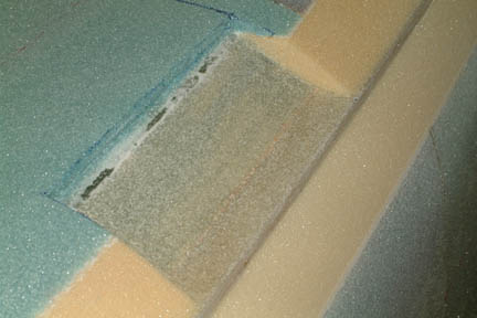
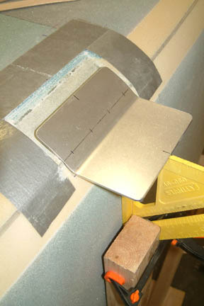
 1)
To do this, I needed the step NOW and not
till chapter 8. I drove down to Ken Brock Mfg. and
picked one up (Its good to live close to approved suppliers). With the step on
hand, I marked the new cavity area to accommodate the intended step position.
Note the bolt positions (indicated by the dark line) on the step. Refer to
Chapter 8 Fig.11. 1)
To do this, I needed the step NOW and not
till chapter 8. I drove down to Ken Brock Mfg. and
picked one up (Its good to live close to approved suppliers). With the step on
hand, I marked the new cavity area to accommodate the intended step position.
Note the bolt positions (indicated by the dark line) on the step. Refer to
Chapter 8 Fig.11. |
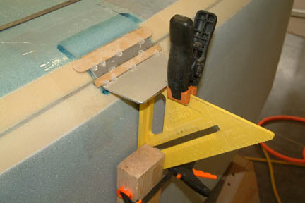
 2)
I expanded the cavity (marked by blue rectangle above) to accommodate the
eventual step bolting position. Note the alignment of the bolt line relative to
the longeron line (left). 2)
I expanded the cavity (marked by blue rectangle above) to accommodate the
eventual step bolting position. Note the alignment of the bolt line relative to
the longeron line (left).
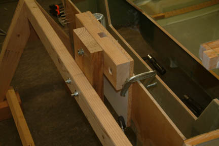
3) I built a vertical support along the side of the fuselage (yellow square) to ensure the horizontal position for the step. This will also be used to secure the step during the flox curing stage.
4) I hot glued two mixing sticks onto the outside surface of the step. This will help me to determine the depth position of the step on top of the flox.
|
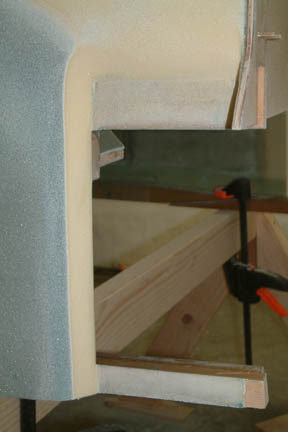
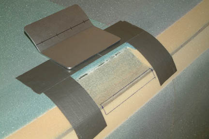
 5)
I covered the inside of the step with clear packing tape for mold release. I
also replaced the duct tape with clear packing tape because they are thinner -
creating an un-noticeable step between the foam and flox. The clamp on the
square functions as a stop - to keep the step from sliding off. 5)
I covered the inside of the step with clear packing tape for mold release. I
also replaced the duct tape with clear packing tape because they are thinner -
creating an un-noticeable step between the foam and flox. The clamp on the
square functions as a stop - to keep the step from sliding off.
6) I wet out a strip of peel ply onto the inside (curved part) of the step. The peel ply is to prepare the flox surface for subsequent glassing of the fuselage bottom. The peel ply will not stick to the packing tape on the step. |
 7) I filled the entire cavity with flox and pressed the step onto it until the mixing sticks hit the foam. I also shaped the remaining flox (areas) as the neighboring foam contour. Peel ply was added.
8) I was going to weigh down the step lightly. However, the suction of the flox held the step in place nicely - I decided to leave it alone for cure. |
 Once the
flox was cured, I removed the mixing sticks, and the packing tape. The
step is now
flush with the foam and the drill holes line up to the lower longerons. The
step will be set aside while the bottom is being glassed. The depression formed
by this deviation, should provide a flush step in Chapter 8. Once the
flox was cured, I removed the mixing sticks, and the packing tape. The
step is now
flush with the foam and the drill holes line up to the lower longerons. The
step will be set aside while the bottom is being glassed. The depression formed
by this deviation, should provide a flush step in Chapter 8. |
There
are more antenna layout variations amongst the Cozy builders than anything I
built up to this point. I think its because we all have different
instrumentation in mind and that the plans pretty much left it to the builders
discretion. After searching through the archives and talking to various RF
engineers and HAM enthusiasts, I have decided on the following layout. The
reason I have so much time on my hands was because I did not order the antenna
kit from RST Engineering ahead of time until I needed the materials. Oshkosh was
around the corner and no one was around to respond ![]() .
Therefore, order your materials early - I ended up ordering the electric landing
brake and main landing gear ahead, just in case...
.
Therefore, order your materials early - I ended up ordering the electric landing
brake and main landing gear ahead, just in case...
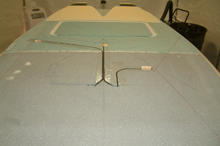
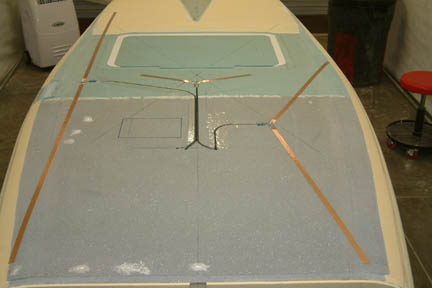
I decided to mount three (3) antennas on the fuselage bottom - the NAV#1, Glide Slope and Marker Beacon. I also plan on adding NAV#2 (and whatever else) on the bottom of the canard. Of course, I will mount the 2 COM antenna on the winglets per plan. I set a few criteria prior to laying out the antenna:
  1)
Make sure to make room for the landing light; 1)
Make sure to make room for the landing light;2) Keep the antenna tip from going through large metal structures (engine) or warm bodies for line of sight communication ; 3) Orientation of the 2 NAV antennas will be 90o from each other for best coverage. 4) The cable entry point will be behind the instrument panel.
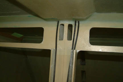
As shown above, I first drew out the landing light position per plan (the rectangular box under the pilot seat), even though I was considering nose lights instead (just in case I change my mind later). Then I translated the instrument panel position onto the bottom of the fuselage. The cables will come up right against the forward wall of the instrument panel and up the insides of the cable braces. Once drawn, the layout was quite easy. The turning radius for the cables are 3" or greater. I routed out the trough for the RG58A/U coax cables with a 3/16" rounded tip Dremel bit for best fit. They turned out a bit tight, but the 1/4" were too loose for my comfort. Note my NAV#1 antenna is on the passenger side to avoid the metal foot step (on the pilot side) and is pointed at 90o to the canard (where NAV#2 is going to go). |
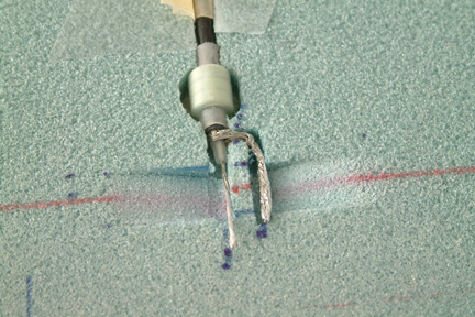  I
prepared the coax cables for soldering onto the copper foils and shrink
sleeved
the ferrite triodes per instructions in the archives. I confirmed with a couple RF engineers that spacing between the triodes are not necessary - therefore, I
just stack them together. Note that toroids are 3/8" in diameter - happens
to be the same thickness as the underlying (blue) foam. Adding the thickness of
the shrink
sleeving, the donuts were protruding 0.050" above surface. I
have to bring in the heavy duty router and carefully take the bottom out -
pretty close to bare glass - but I got them to fit without feeling a bump! I
then sloped the foam smooth to support the foil transitioning from the
solder joint (to be floxed in under surface) to the surface of the fuselage. Now
I just get the foils from RST Engineering, and I will be good to go... I
prepared the coax cables for soldering onto the copper foils and shrink
sleeved
the ferrite triodes per instructions in the archives. I confirmed with a couple RF engineers that spacing between the triodes are not necessary - therefore, I
just stack them together. Note that toroids are 3/8" in diameter - happens
to be the same thickness as the underlying (blue) foam. Adding the thickness of
the shrink
sleeving, the donuts were protruding 0.050" above surface. I
have to bring in the heavy duty router and carefully take the bottom out -
pretty close to bare glass - but I got them to fit without feeling a bump! I
then sloped the foam smooth to support the foil transitioning from the
solder joint (to be floxed in under surface) to the surface of the fuselage. Now
I just get the foils from RST Engineering, and I will be good to go... |
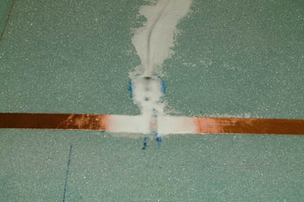
 The
copper foil and new toroids finally arrived and I put them in without much
difficulty. I did a few trial runs on soldering onto the copper foil to make
sure I got it right - it was not too tough. I taped copper foils onto the
fuselage per my layout, cut them to length per RST's recommendations and
soldered the coax leads in place. I also did a continuity test on each of the
connections to make sure they are not broken or shorted. I mixed some wet micro
and 'pot' the connections in place. I then sanded them to foam level after
cure. The
copper foil and new toroids finally arrived and I put them in without much
difficulty. I did a few trial runs on soldering onto the copper foil to make
sure I got it right - it was not too tough. I taped copper foils onto the
fuselage per my layout, cut them to length per RST's recommendations and
soldered the coax leads in place. I also did a continuity test on each of the
connections to make sure they are not broken or shorted. I mixed some wet micro
and 'pot' the connections in place. I then sanded them to foam level after
cure. |
| Helping Hands |
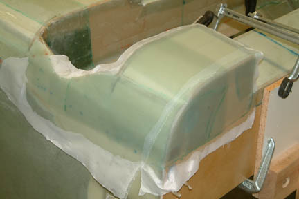
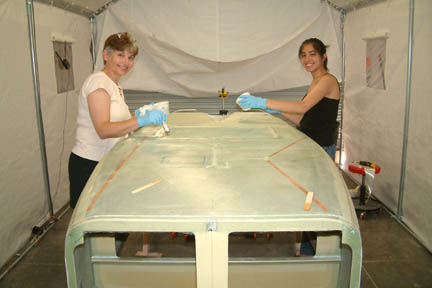 Our
younger daughter was visiting home during her summer break from UC Santa Barbara
and she decided to give us a helping hand on a large layup (the fuselage
bottom). Nothing beats hands on experience especially for a mechanical
engineering major! It took us a good part of the day to get it done. I sure
enjoyed the participation and 'quality time' Our
younger daughter was visiting home during her summer break from UC Santa Barbara
and she decided to give us a helping hand on a large layup (the fuselage
bottom). Nothing beats hands on experience especially for a mechanical
engineering major! It took us a good part of the day to get it done. I sure
enjoyed the participation and 'quality time' |
| Contouring Upper Longerons |
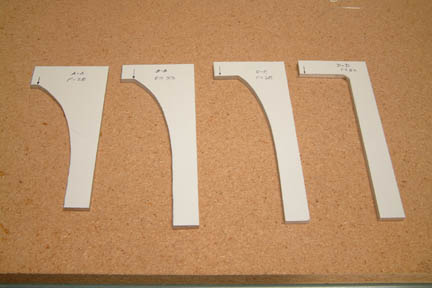 We were
given 4 templates for shaping / contouring the upper longerons. I have to read
the instructions and clarifications several times before I figured it out - a
bit slow these days We were
given 4 templates for shaping / contouring the upper longerons. I have to read
the instructions and clarifications several times before I figured it out - a
bit slow these days Template A was used at F22; Template B was used at F28; Template C was used FROM F33 (3" front of instrument panel) to edge of front seat back; and Template D was used at the start of the curvature to the center spar cutout (see picture below). |
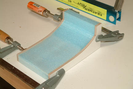 Since
Template C was to be used at quite a distance (~ 27" along the longerons),
I decided to make a contouring sanding pad again (as I did for the bottom fuselage). I made 2 sets of Template C, clamped them against a block of foam and
carved out the foam block with a hot wire. Using double sided tape, I attached
a sheet of sand paper onto the foam and sanded away from F33 to ~F60. Since
Template C was to be used at quite a distance (~ 27" along the longerons),
I decided to make a contouring sanding pad again (as I did for the bottom fuselage). I made 2 sets of Template C, clamped them against a block of foam and
carved out the foam block with a hot wire. Using double sided tape, I attached
a sheet of sand paper onto the foam and sanded away from F33 to ~F60.
|
 I
marked the contour lines such that I knew when to start and stop. As discussed
above, Template A is at F22 (foremost), Template B is at the middle mark and
Template C starts at the third mark and on. I
marked the contour lines such that I knew when to start and stop. As discussed
above, Template A is at F22 (foremost), Template B is at the middle mark and
Template C starts at the third mark and on.
The gradual curvature was drawn at F22 (front) for reference. |
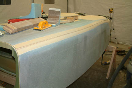
 The
result can be seen here. It was a bit difficult to keep both sides exact,
especially between Template A to B and then B to C. However, the contouring tool
for Template C made both sides pretty even from Template C and on... The
result can be seen here. It was a bit difficult to keep both sides exact,
especially between Template A to B and then B to C. However, the contouring tool
for Template C made both sides pretty even from Template C and on...
|
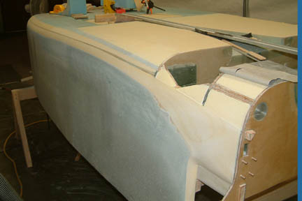
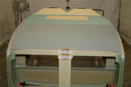
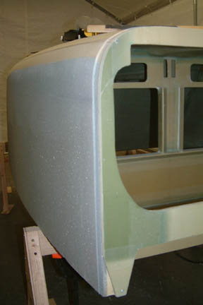
 A
picture of the full contour is shown on the left. Template D was used at the
start of the foam curvature for the center spar cutout. I drew a straight line
from Template C (i.e. the edge of the front seat back) to Template D to guide my
contouring effort. A
picture of the full contour is shown on the left. Template D was used at the
start of the foam curvature for the center spar cutout. I drew a straight line
from Template C (i.e. the edge of the front seat back) to Template D to guide my
contouring effort. |
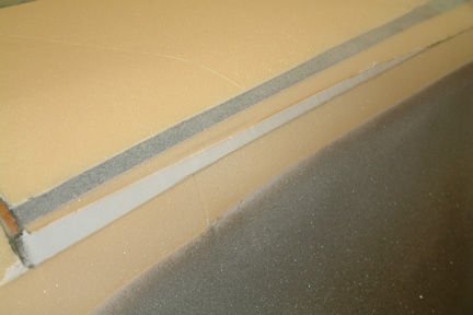
| Rotisserie |
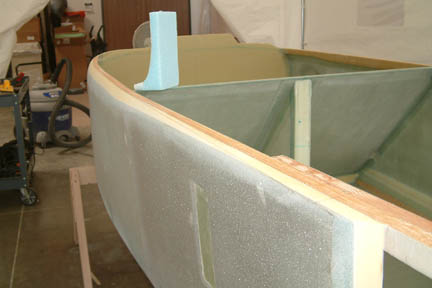
 The
next task was to build a rotisserie such that I can rotate the fuselage on its
axis for the next few operations. Instead of building a whole new support
structure, I made some modifications/additions to the existing saw horses and got
my rotisserie reasonably quick and inexpensive. Here's the picture of the
front end rotisserie. The
next task was to build a rotisserie such that I can rotate the fuselage on its
axis for the next few operations. Instead of building a whole new support
structure, I made some modifications/additions to the existing saw horses and got
my rotisserie reasonably quick and inexpensive. Here's the picture of the
front end rotisserie. |
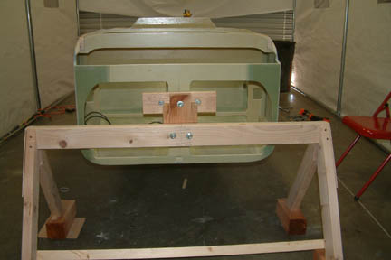
 Here's the picture of the back end of the rotisserie. Note the slot on the top of the rotisserie - that's the wrench access for the locking bolt.
Somehow I forgot to take pictures after I finished glassing the sides. It took me and Susann around 4-6 hours each to finish! |
| Reinforcement Layup |
 The last item in this chapter was to add 3 plies UND reinforcement to the engine mount and hard point. The length of the glass was to be 8,10 & 12" beyond the firewall edges. However, the picture in Fig. 24 showed the plies go way past the landing gear openings. I was a bit confused but decided to follow the instructional dimensions instead of the picture.
That's
the end of Chapter 7 and onto Chapter 8... |