 In this chapter,
we will construct the shoulder support, headrests, the aft heat duct, hard
points for seat belts and shoulder straps. This is a relatively short but
important chapter because they deal with safety features on the plane.
In this chapter,
we will construct the shoulder support, headrests, the aft heat duct, hard
points for seat belts and shoulder straps. This is a relatively short but
important chapter because they deal with safety features on the plane.| What's up? |
| In this chapter,
we will construct the shoulder support, headrests, the aft heat duct, hard
points for seat belts and shoulder straps. This is a relatively short but
important chapter because they deal with safety features on the plane. |
| Head Rest |
 The
first item to be built was the headrest. They are kind of goofy looking triangles
sticking up behind the pilot and passenger's heads. I presume the high headrest
is to protect the passengers' heads in the event of a roll over. Regardless, here's
how I held them in place for curing. I had a real tough time wrapping the
glass over the rounded corners at the top. I ended up adding flox and rounded them
off by sanding. My workmanship on these pair was so so... Fortunately, I do
not have to glass them in right away (per instruction). I will be going to Rough
River (a popular Canard Fly In every year) later this week and see how others
built theirs. Meanwhile I completed them and put them in storage. The
first item to be built was the headrest. They are kind of goofy looking triangles
sticking up behind the pilot and passenger's heads. I presume the high headrest
is to protect the passengers' heads in the event of a roll over. Regardless, here's
how I held them in place for curing. I had a real tough time wrapping the
glass over the rounded corners at the top. I ended up adding flox and rounded them
off by sanding. My workmanship on these pair was so so... Fortunately, I do
not have to glass them in right away (per instruction). I will be going to Rough
River (a popular Canard Fly In every year) later this week and see how others
built theirs. Meanwhile I completed them and put them in storage. |
 [Hindsight]
I am currently working on Chapter 25 and getting close to
fill, sand and paint the interior. I decided to dig out the headrests I made (per
Plan) and put them in place. I was surprised to see how big those headrests are
when put in place. No wonder many builders switch over to automotive headrests.
I also heard complaints from Cozy flyers that their head rolls off the edge of
the headrest, especially if you are a tall person. [Hindsight]
I am currently working on Chapter 25 and getting close to
fill, sand and paint the interior. I decided to dig out the headrests I made (per
Plan) and put them in place. I was surprised to see how big those headrests are
when put in place. No wonder many builders switch over to automotive headrests.
I also heard complaints from Cozy flyers that their head rolls off the edge of
the headrest, especially if you are a tall person.
I was under the impression that the headrests are not designed for head protection (roll bar equivalent). I know of many Cozy flyers using auto headrests or none at all - for one reason or another. So, I decided to make a set of smaller and light weight headrests in place of the original set.
|
 My
new headrest has the same width (8") as the base dimension of Plans' version. However, it is
a 6"
tall curved rectangular shape instead of triangular. It has a slight curvature to keep one's
head from rolling off the edges. The challenge was to find a big curvature to
form the foam and glass. I had a curved Plexiglas office partition - perfect!
See how I use the partition to form a slight curvature to my new headrest?
After all the trimming, it actually turned out quite nice. My
new headrest has the same width (8") as the base dimension of Plans' version. However, it is
a 6"
tall curved rectangular shape instead of triangular. It has a slight curvature to keep one's
head from rolling off the edges. The challenge was to find a big curvature to
form the foam and glass. I had a curved Plexiglas office partition - perfect!
See how I use the partition to form a slight curvature to my new headrest?
After all the trimming, it actually turned out quite nice. |
 [More
Hindsight] While making the alternative headrests (above), I got talked out of this approach by yet other Cozy builders that
the Plan's headrests are 'sort of' head protection. After some more thought, I
decided to go back to the original Plan [More
Hindsight] While making the alternative headrests (above), I got talked out of this approach by yet other Cozy builders that
the Plan's headrests are 'sort of' head protection. After some more thought, I
decided to go back to the original Plan
|
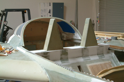
 Here's
a picture of the pilot's headrest glassed onto the canopy frame per Plan. Note
the extra storage space I made available for in-flight access. Here's
a picture of the pilot's headrest glassed onto the canopy frame per Plan. Note
the extra storage space I made available for in-flight access.
You can see more pictures of my headrest in Chapter 25 Section 3A (finishing). |
| Shoulder Rest |
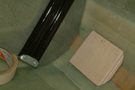
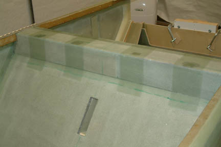
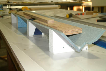 The
shoulder rest gets mounted along the top edge of the front seat back. It acts as
a platform for the head rests to sit one and the hard points for mounting the
shoulder harness. I built it a bit out of sequence. I built the foam fixture (as
shown) and microed the inside corners before glassing.
The boards were there to hold the foam strip flat and straight while the micro
is being cured. I then
installed the 4 hard points (not shown) before bonding it onto the top of the
front seat back, but wait, I need to drill holes on the front seat back and
install the canopy hinges first...(because one of the bolts for the hinge will
be covered up by the shoulder rest). The
shoulder rest gets mounted along the top edge of the front seat back. It acts as
a platform for the head rests to sit one and the hard points for mounting the
shoulder harness. I built it a bit out of sequence. I built the foam fixture (as
shown) and microed the inside corners before glassing.
The boards were there to hold the foam strip flat and straight while the micro
is being cured. I then
installed the 4 hard points (not shown) before bonding it onto the top of the
front seat back, but wait, I need to drill holes on the front seat back and
install the canopy hinges first...(because one of the bolts for the hinge will
be covered up by the shoulder rest). |
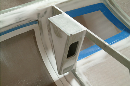
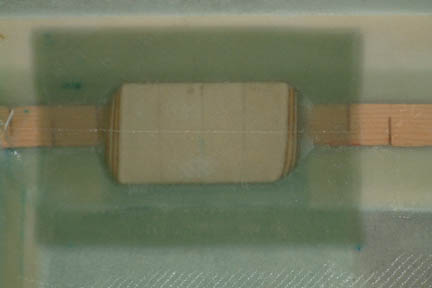
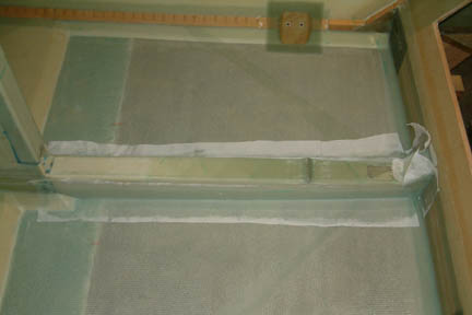
 Once
the micro on the corner was cured, I proceeded to cut out the square hard
points, fit them into the foam per instruction. At this point of construction,
they should be easy for all of us builders. I went ahead and glassed the hard
points at this time because of the easy access compared to plan instruction to
install the glass after the shoulder rest is installed onto the front seat back.
Here's a picture of my shoulder rest after the hard points are glassed in. Once
the micro on the corner was cured, I proceeded to cut out the square hard
points, fit them into the foam per instruction. At this point of construction,
they should be easy for all of us builders. I went ahead and glassed the hard
points at this time because of the easy access compared to plan instruction to
install the glass after the shoulder rest is installed onto the front seat back.
Here's a picture of my shoulder rest after the hard points are glassed in.
Important Note: I put a
sheet of plastic on the under side of the foam while installing the square hard
points such that the flox (that oozed out) would not stick to the table top. You
can imagine the fun you'll have digging the shoulder rest free |
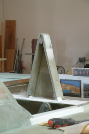
| Canopy Hinges |
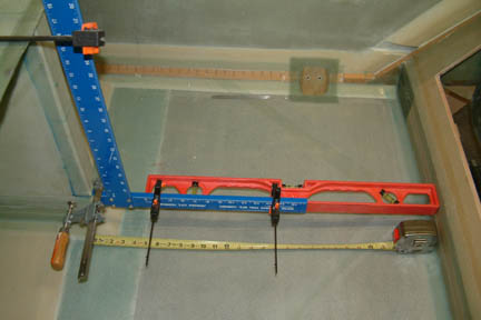
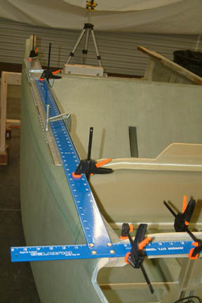 The
hinges were easier to install than it sounds. The key is to line it up perfectly
before floxing them in place. I did not use the 4' level (per instruction)...
instead, I mounted a long T-square against F22 and then slid the long edge
(left & right) parallel to the upper longeron for a satisfactory position.
This allows me to find a good place for the bolts to go through the upper
longerons AND that the hinges will be parallel to the centerline of the
plane. The
hinges were easier to install than it sounds. The key is to line it up perfectly
before floxing them in place. I did not use the 4' level (per instruction)...
instead, I mounted a long T-square against F22 and then slid the long edge
(left & right) parallel to the upper longeron for a satisfactory position.
This allows me to find a good place for the bolts to go through the upper
longerons AND that the hinges will be parallel to the centerline of the
plane.
I then slid the piano hinge plate under the T-square with its hinges butt along the straight edge. After I confirmed its positions per instruction, I put a temporary length of piano hinge in between the permanent ones and slid a long pin through all three hinges - just for alignment verification. I then applied flox under the permanent hinges and clamped them down for cure (as shown).
To avoid
flox getting onto the hinges, I taped them down with packing tape. As I found
out later, the packing tape left a real sticky residue on the metal surfaces. I
tried removing them with razor blade, alcohol, acetone and vinegar no luck.
Finally I tried paint thinner and it worked wonderfully. It removed all the glue
residue ... including the markings on the piano hinges
Since the hinges are straight and the upper longerons are curved, the bolt hole positions are not as straight forward. I was debating if they should line up with the hinges or line up along the center line of the longerons. Eventually, I drew two intersecting lines - one along the center of the hinge plate and the other along the center of the longeron. I drilled the bolt holes somewhere in between the 2 lines. They turned out OK. |
Per plan instructions, the canopy hinges will be installed out of sequence (Chapter 18). I had a difficult time to reconcile the bolts, nuts & washers for the hinges when ordering the material kits for Chapter 8 only. The bolts I got were not the exact part number as the ones called out in Chapter 18. I finally decided to re-order the bolts, nuts AND washers from Chapter 18 for this installation.
This is the first time (throughout this construction process) to work with the aircraft type of bolts and nuts. When I received the bolts and nuts from Aircraft Spruce, I found the nuts would not screw onto the bolts easily. I can finger turn the nut in about 1 to 2 turns, then I have to resort to screw driver and wrench to continue. That doesn't seem normal to me because I took a standard 10-32 nut from Home Depot and I can spin the nut right up the bolt easily. Based on all the horror stories I heard from the Cozy forum about Aircraft Spruce (though I had very good experiences with them), I was beginning to wonder if I had the wrong part. After conferring with other builders and machinists, I learned that the nuts were Intentionally squeezed a bit to prevent the nut from backing out during vibration. If you hold up the nut and rotate it (while looking through the hole), you can see the hole is a bit oval in shape. Never hurts to double check when in doubt...
| Seat Belt Hard Points |
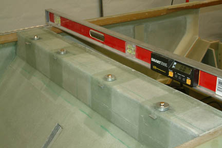
 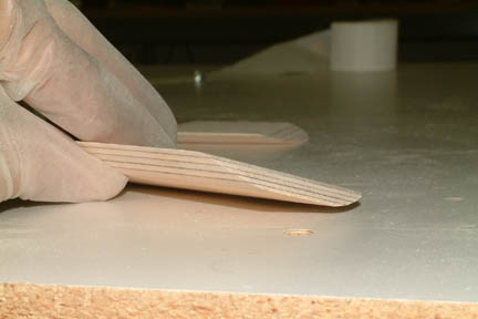 The
4 outside seat belt hard points will be installed along the lower longerons. The
front left is a bit different then the others because the external foot step
will be anchored to it as a single unit. The plan calls for fabricating 4
1/4" thick birch ply wood inserts which fit fairly well against the
longerons. Since the internal shape
along the lower longerons varies at each of those 4 points (let alone various
builders), I expect these inserts will require some customization. Again, I
turned to my carpenter widget (as shown) to establish my cross-sectional profile
of the inserts. I transferred the profile onto the inserts, then trimmed and sanded
as needed. In addition, I also sloped the top of the inserts such that the 7
layers of glass will lay down nicely. The resultant shape of the insert is
somewhat complex (as shown), but they all fit well along the
longerons. The
4 outside seat belt hard points will be installed along the lower longerons. The
front left is a bit different then the others because the external foot step
will be anchored to it as a single unit. The plan calls for fabricating 4
1/4" thick birch ply wood inserts which fit fairly well against the
longerons. Since the internal shape
along the lower longerons varies at each of those 4 points (let alone various
builders), I expect these inserts will require some customization. Again, I
turned to my carpenter widget (as shown) to establish my cross-sectional profile
of the inserts. I transferred the profile onto the inserts, then trimmed and sanded
as needed. In addition, I also sloped the top of the inserts such that the 7
layers of glass will lay down nicely. The resultant shape of the insert is
somewhat complex (as shown), but they all fit well along the
longerons. |
 I
spread a bunch of flox under the inserts and pressed down evenly until flox
started to ooze out from all directions. I wiped off all the excess flox around
the inserts and laid down the seven (7) layers of BID per plan over all 4 inserts. Instead of laying
7 BID layers, one at a time, I made two (2) sets of bid tapes - 3 & 4 layers
respectively. The reason for doing so is that I can wet out the BID tapes
quicker and the layers line up better
(just for cosmetic reasons). In addition, a 7 layer BID tape may not conform
onto the inserts readily. The result looked good - no trapped air bubbles, the
edges are lined up nicely and the peel ply provided a smooth transition onto the
fuselage surface. I
spread a bunch of flox under the inserts and pressed down evenly until flox
started to ooze out from all directions. I wiped off all the excess flox around
the inserts and laid down the seven (7) layers of BID per plan over all 4 inserts. Instead of laying
7 BID layers, one at a time, I made two (2) sets of bid tapes - 3 & 4 layers
respectively. The reason for doing so is that I can wet out the BID tapes
quicker and the layers line up better
(just for cosmetic reasons). In addition, a 7 layer BID tape may not conform
onto the inserts readily. The result looked good - no trapped air bubbles, the
edges are lined up nicely and the peel ply provided a smooth transition onto the
fuselage surface. |
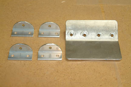 I
cut out the seat belt anchor (brackets) with a jig saw and drilled the bolt
holes with the drill press. I rounded the top of the brackets off with the help
of a template (drawn with Microsoft Corel) and a 12" sanding disc. My
next step was to install the bolts through the inserts. I found all the bolts
called out in the plans were too short. I ended up ordering a whole new set of
longer bolts and screws such that the end of the bolts will protrude above the nut by
at least a couple of turns. Here's a picture of the pre-drilled external step
and the seat belt brackets. I
cut out the seat belt anchor (brackets) with a jig saw and drilled the bolt
holes with the drill press. I rounded the top of the brackets off with the help
of a template (drawn with Microsoft Corel) and a 12" sanding disc. My
next step was to install the bolts through the inserts. I found all the bolts
called out in the plans were too short. I ended up ordering a whole new set of
longer bolts and screws such that the end of the bolts will protrude above the nut by
at least a couple of turns. Here's a picture of the pre-drilled external step
and the seat belt brackets. |
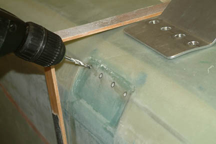 One of the biggest concerns I have was to make
sure the holes of the step (external) lines up with the corresponding seat belt
bracket (internal), especially when drilling the holes through the fuselage. I came up with
a simple approach to guide my drill. I taped two (2) sanding sticks along the
side and bottom of the fuselage, forming a ~90 degree angle relative to the
bottom longeron. I then lined up the drill bit from the corner (formed by the
sanding sticks) to the pre-marked hole location. They came out consistently on
the other side and lined up perfectly with seat belt brackets One of the biggest concerns I have was to make
sure the holes of the step (external) lines up with the corresponding seat belt
bracket (internal), especially when drilling the holes through the fuselage. I came up with
a simple approach to guide my drill. I taped two (2) sanding sticks along the
side and bottom of the fuselage, forming a ~90 degree angle relative to the
bottom longeron. I then lined up the drill bit from the corner (formed by the
sanding sticks) to the pre-marked hole location. They came out consistently on
the other side and lined up perfectly with seat belt brackets |
 After
the holes were drilled, I bought a 1/2" counterbore bit from the internet (that can mount onto a
1/4" drill bit). I used it to put the counterbores for the
anchor bolts. Counterbore for the front right seat was straight forward because
the lower longeron was close to the surface. I hit wood quickly and was able to
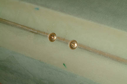
put a nice flat surface for seating the anchor bolt head. After
the holes were drilled, I bought a 1/2" counterbore bit from the internet (that can mount onto a
1/4" drill bit). I used it to put the counterbores for the
anchor bolts. Counterbore for the front right seat was straight forward because
the lower longeron was close to the surface. I hit wood quickly and was able to
put a nice flat surface for seating the anchor bolt head.
[Hindsight] The AN4 bolts called out in the Plans may not be long enough. I did not find this out until I was mounting my seat belts - after Chapter 25 (filled, sand and primed). The protruding thread (between .235" to .335") was not long enough to accommodate the .125" thick bracket, the squeezed nut (.214" thick), plus two threads (.071"). Drilling them back out is out of the question at that point. My solution is discussed below... |
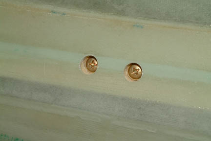 As for
the counterbores for the rear seat belts, the lower longerons are much deeper
from the surface. I made sure I counterbored deep enough (through the foam) until
I hit solid wood and provided a flat seating surface for the anchor bolt heads.
The foam between the glass and the lower longeron is not going to be much of a
structure as far as a safety belt is concerned. I think these counterbore holes will
get filled up eventually - hopefully I am right. As for
the counterbores for the rear seat belts, the lower longerons are much deeper
from the surface. I made sure I counterbored deep enough (through the foam) until
I hit solid wood and provided a flat seating surface for the anchor bolt heads.
The foam between the glass and the lower longeron is not going to be much of a
structure as far as a safety belt is concerned. I think these counterbore holes will
get filled up eventually - hopefully I am right. |
I did not start mounting my seat belts until I completed Chapter 25. As mentioned above, the Plans recommended bolts were too short for MY hard points. So, to avoid what I have to do below, make sure you have a longer bolt before floxing and glassing them in. In the event you missed it as I have, here's my thought process and eventual save the day effort...
First Idea -
shave down the bottom of the bracket by 1/16". I didn't like that idea because
it will weaken the bracket for a life saving device (seat belts)
![]() .
.
Second Idea -
make a 1/16" steel bracket instead. Hard to find 1/16" steel angle
extrusion, too much work to re-do all 4 brackets...![]() again!
again!
Third Idea -
make a recess on the Plans aluminum bracket, use a thin nut/safety wire clip
combination. Not a good idea because thin nut reduces the number of engaged
threads. Not for my safety belt...![]() again!
again!
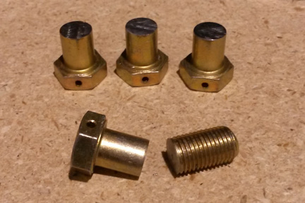
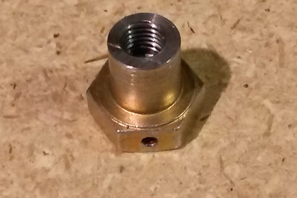
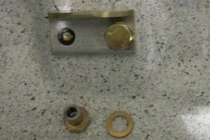
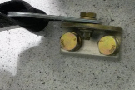
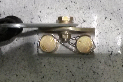
Forth Idea:
- Measure the length of extruded threads. They are around 0.235" to .335" long;
- Cut off the thread section of AN6-7 bolts (your mileage may vary) with drilled caps for safety wire (picture #1 );
- Drill and tap the bolt grip with 1/4-28 thread. This will be used as a cap over the protruded 1/28 threads (picture #2);
- Enlarge the existing holes on the aluminum brackets to 3/8" diameter to allow the AN6 bolts (picture #3);
- Added extra washers or 1/8" thick back plate to take up the space between the bracket and AN6 bolt head (picture #4);
- Safety wire the two bolts together (picture #5).
 |
 |
 |
 |
 |
| Glassing the Shoulder Rest |
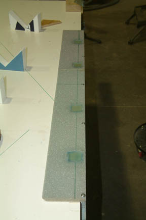
 While
waiting for the delivery of the new bolts and screws, I decided to glass in the
shoulder rest. I made a glass tape for the inside surface of the shoulder rest
but forgot to leave the outside edges of the glass free of epoxy (per plan). I waited for
only one hour (for the epoxy to form) before I attached it onto the front seat back. Hopefully, the glass
will not detach from the foam. Guess I'll find out when installing the shoulder
belt bolts... I left it to cure overnight. While
waiting for the delivery of the new bolts and screws, I decided to glass in the
shoulder rest. I made a glass tape for the inside surface of the shoulder rest
but forgot to leave the outside edges of the glass free of epoxy (per plan). I waited for
only one hour (for the epoxy to form) before I attached it onto the front seat back. Hopefully, the glass
will not detach from the foam. Guess I'll find out when installing the shoulder
belt bolts... I left it to cure overnight.
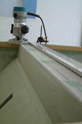
I
removed all the peel ply (the next day) and rounded off the
front edge of the shoulder rest in preparation for glassing the top layers. I
just set up the router and made 3/16" radius along the front edge -
remember Chapter 3
(education)? BTW, don't forget the four (4) strips of 3 plies over the shoulder
hard points - they are in fine print. I got a few long bubble strips along the
back side of the enforcement strips when wrapping around the back edge of the
seat. I should have rounded off the back edge of the seat while I was at it on
the front but decided against it because it wasn't called out in the plans. Now
I have to drill them out and fill them with epoxy. Live and learn...
|
I was not looking forward to mounting the shoulder belt anchors. Plan instructions required us to punch a hole through the front face of the shoulder rest and slip a nut plate under the shoulder belt hard points and match up with the anchor bolt. I made the mistake of not reading the FAQ for Chapter 8 before glassing the shoulder rest onto the front seat back. Others have successfully installed the bolt and nut plate PRIOR to glassing the shoulder rest onto the front seat back - now I may have to pay for it with unnecessary effort - but there's no turning back. On the other hand, following the plans normally guarantees success...
 First, I made the 4 nut plates per plan. I
have to refer back to Chapter 6 and see how I did it for the fuel selector.
Somehow, I forgot to take pictures of the nut plates. Once
completed, I projected the center lines of the 4 hard points down the front face
of the shoulder rest. If you look close at the picture (left), you should be
able to make out the penciled center line. Based on the thickness of the foam and glass, I can
establish the position of the horizontal slot (I needed to cut) for the nut
plate to slide into. Directly under the horizontal line I marked a center point
for a 3/8" hole. First, I made the 4 nut plates per plan. I
have to refer back to Chapter 6 and see how I did it for the fuel selector.
Somehow, I forgot to take pictures of the nut plates. Once
completed, I projected the center lines of the 4 hard points down the front face
of the shoulder rest. If you look close at the picture (left), you should be
able to make out the penciled center line. Based on the thickness of the foam and glass, I can
establish the position of the horizontal slot (I needed to cut) for the nut
plate to slide into. Directly under the horizontal line I marked a center point
for a 3/8" hole.
Starting with the hand drill, I drilled the 4
(3/8") holes on the front face of the shoulder rest. Then I used a jig saw
and re-shaped the round holes into square holes. Right along the top edges of the
square holes, I cut out the 3/4" horizontal slots to accommodate the
aluminum plates (that the nuts are riveted onto). I re-checked the hole
locations against the center of the hard points to make sure they are still
aligned. Then I drilled the 1/4" holes through the center of the 4 hard
points. Surprisingly, the drilling and shaping of the holes were not as
difficult nor time consuming as I anticipated. Once completed, I slipped the nut plates through the slots
while peeking through the anchor holes from the top. Magically, they lined up
perfectly... |
 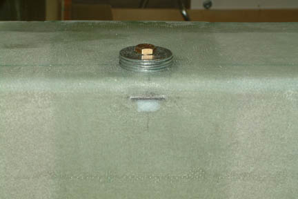 I spread
flox on the aluminum surfaces around the
nut, slipped it through the slot/hole and engaged the nut plate with the anchor
bolt from the top. I added several thick washers under the bolt to help pull the
nut plate up against the bottom surface of the shoulder rest - to assure good contact
for the flox. Then I filled the square holes with
additional flox and smoothed them out with a thin credit
card. Once cured, I used a hack saw and cut off the excess tab (picture
right). As you can see, the holes are not too big
and I should be able to hide them easily with a layer of glass. I
can see one advantage of this method
- the nut plates are affixed & floxed in the horizontal slots and it is not going to
rotate no matter how hard you turn the anchor bolts down the
road. I spread
flox on the aluminum surfaces around the
nut, slipped it through the slot/hole and engaged the nut plate with the anchor
bolt from the top. I added several thick washers under the bolt to help pull the
nut plate up against the bottom surface of the shoulder rest - to assure good contact
for the flox. Then I filled the square holes with
additional flox and smoothed them out with a thin credit
card. Once cured, I used a hack saw and cut off the excess tab (picture
right). As you can see, the holes are not too big
and I should be able to hide them easily with a layer of glass. I
can see one advantage of this method
- the nut plates are affixed & floxed in the horizontal slots and it is not going to
rotate no matter how hard you turn the anchor bolts down the
road. |
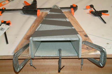
| Rear Heat Duct |
|
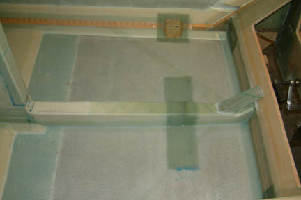
Took a bit of pondering before I figured out how to establish the bottom profile of the rear heat duct. I first laid a laser along the sides of the forward heat duct and projected it rearwards onto the landing gear bulkhead. I marked the laser lines with a pencil onto the surface of the fuselage. These pencil lines established the 'footprint' for the rear heat duct.
I took those dimensions and re-created the profile on a piece of paper. Connected the dots with my un-official giant French curve (a long strip of Formica). Then I placed the paper on top of the foam and transferred the profile with my tracing wheel. Trimmed the foam sides with a blade and floxed them together - forming the rear heat duct. Then I trial fit it in place and with minor shaping, I was able to make it from good to nice fit! |
| Mounting and Glassing the 3/8" Tubing |
 When
I mounted the 3/8" tubing onto the forward heat duct in Chapter 6, I prepared
the foam (where the tubing sits) by wrapping a piece of sand paper around a wood
dowel and sanded away. This time, I just took a 3/8" drill bit, mount it on
my drill press and turned it on. I pre-marked the tube location on the rear
heat duct, then pressed it against the drill bit. I ended up with a nice curvature
that hugs the 3/8" tubing perfectly. It took about 2 minutes for the entire
operation. When
I mounted the 3/8" tubing onto the forward heat duct in Chapter 6, I prepared
the foam (where the tubing sits) by wrapping a piece of sand paper around a wood
dowel and sanded away. This time, I just took a 3/8" drill bit, mount it on
my drill press and turned it on. I pre-marked the tube location on the rear
heat duct, then pressed it against the drill bit. I ended up with a nice curvature
that hugs the 3/8" tubing perfectly. It took about 2 minutes for the entire
operation.
I floxed the tubing in place making sure I have a long shallow sloped fillet along the sides of the tubing (I remembered the difficulty I had glassing over it the last time). I then glassed the tubing in place per plan. Note the smooth transition along the sides of the tubing this time.
|
 When
floxing and taping the heat duct in place, I used the same technique as the
lower longerons (I learned this technique from John Slade's site). I first
applied relatively dry flox under and along the edges of the heat duct. Then I
brushed (lightly) pure epoxy over the dry flox. You can see the flox conforms to a
nice smooth fillet for the glass tape. Then I applied the 2 layers BID tape
before the flox got a chance to cure. You will get a very nice and smooth tape
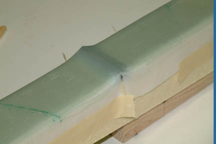
joint. You can see the result in the picture (below). When
floxing and taping the heat duct in place, I used the same technique as the
lower longerons (I learned this technique from John Slade's site). I first
applied relatively dry flox under and along the edges of the heat duct. Then I
brushed (lightly) pure epoxy over the dry flox. You can see the flox conforms to a
nice smooth fillet for the glass tape. Then I applied the 2 layers BID tape
before the flox got a chance to cure. You will get a very nice and smooth tape
joint. You can see the result in the picture (below). |
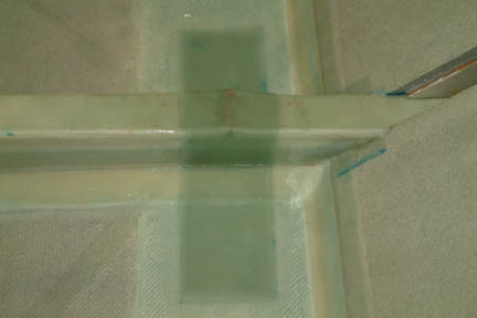
 The
next step is to add 7 plies of tapes (alternating BID and UND) across the heat
duct at the tubing. The plan suggested trimming the plies both height and width
for feathering the peel ply stack. At first I considered taking 1/8" off
each side between layers for feathering. However, by the time I got to the top
layer, the width of the ply will only be 2 1/2" wide. I was not comfortable
with that especially if it is for the safety belt. I decided to make the width of
the first 3 plies the same (4"), then the next 3 plies (3 3/4") wide
and the last ply 3 1/2"
wide. The
next step is to add 7 plies of tapes (alternating BID and UND) across the heat
duct at the tubing. The plan suggested trimming the plies both height and width
for feathering the peel ply stack. At first I considered taking 1/8" off
each side between layers for feathering. However, by the time I got to the top
layer, the width of the ply will only be 2 1/2" wide. I was not comfortable
with that especially if it is for the safety belt. I decided to make the width of
the first 3 plies the same (4"), then the next 3 plies (3 3/4") wide
and the last ply 3 1/2"
wide. |
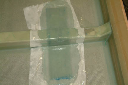
 This is the
first time I used packing wrap over the peel ply (instead of plastic sheets from
Home Depot) to 'seal' the bubbles out. The reason being that I'll have a tough
time getting the plastic sheets to conform to the top of the heat duct (at the
aluminum tube). As expected, the
packing wrap conforms to the heat duct nicely and they stuck to the wet peel ply
readily. I did the same to the front and you can see the result. This is the
first time I used packing wrap over the peel ply (instead of plastic sheets from
Home Depot) to 'seal' the bubbles out. The reason being that I'll have a tough
time getting the plastic sheets to conform to the top of the heat duct (at the
aluminum tube). As expected, the
packing wrap conforms to the heat duct nicely and they stuck to the wet peel ply
readily. I did the same to the front and you can see the result. |
This is
one odd shaped part to make. I just returned from Rough River and attended
Randi's (The CozyGirrrls) lo-vac tutorial. I figure this would be a good
opportunity to try this out. To make a long story short, my part did not
turn out as nice as hers. Evidently, I did not pay enough attention in class ![]() .
I think I was drawing too much vacuum, and that the glass was not directly
attached to the foam (as required per plan). Maybe this is one of those 'not applicable'
applications. I will learn this process in time because I believe it will be a
very valuable technique down the road. Randi...help!!!!
.
I think I was drawing too much vacuum, and that the glass was not directly
attached to the foam (as required per plan). Maybe this is one of those 'not applicable'
applications. I will learn this process in time because I believe it will be a
very valuable technique down the road. Randi...help!!!!
 I was a
bit confused with the positioning of the transition duct. The picture in the
plan shows the round tip lines up with the edge of the heat duct. With the
transition duct being 6" long, I have to cut the transition hole quite a
bit forward. Just doesn't look right to me... Why would the transition
hole be so far from the baffle? Why not call out a shorter transition duct? Well
Marc Zeitlin's and Rick Maddy's web site pictures provided the answer. Here's where
I put mine - leaving ~1/4" gap between the tip of the duct and the slant
wall of the front landing gear bulkhead. I then floxed in the transition tube.
After all is done and cured, I removed all the packing wrap and peel ply. They
turned out reasonably appealing and clean. I was a
bit confused with the positioning of the transition duct. The picture in the
plan shows the round tip lines up with the edge of the heat duct. With the
transition duct being 6" long, I have to cut the transition hole quite a
bit forward. Just doesn't look right to me... Why would the transition
hole be so far from the baffle? Why not call out a shorter transition duct? Well
Marc Zeitlin's and Rick Maddy's web site pictures provided the answer. Here's where
I put mine - leaving ~1/4" gap between the tip of the duct and the slant
wall of the front landing gear bulkhead. I then floxed in the transition tube.
After all is done and cured, I removed all the packing wrap and peel ply. They
turned out reasonably appealing and clean. |
That's
the end of Chapter 8 ![]() ....
onto Chapter 9!
....
onto Chapter 9!
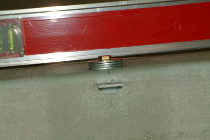
 I used
my long T-square/ruler and stuck one end of the T into the hole above the front
heat duct. With the edge of the T resting on top of the front heat duct, I now
have established the slop of the heat duct (its supposed to be leveled
horizontally) - while the remaining leg of the T projected the slope outward
for the rear heat duct. I extended the T by clamping a straight edge to it (the
red level was just handy at the moment). Then I laid a
measuring tape along the pencil lines. With a ruler, I recorded the height
between the bottom edge of the T and the fuselage surface (at the pencil mark).
I repeated this measurement at 1" intervals - totaling 28 points (remember,
the rear heat duct is suppose to 28 1/8" per plan?).
I used
my long T-square/ruler and stuck one end of the T into the hole above the front
heat duct. With the edge of the T resting on top of the front heat duct, I now
have established the slop of the heat duct (its supposed to be leveled
horizontally) - while the remaining leg of the T projected the slope outward
for the rear heat duct. I extended the T by clamping a straight edge to it (the
red level was just handy at the moment). Then I laid a
measuring tape along the pencil lines. With a ruler, I recorded the height
between the bottom edge of the T and the fuselage surface (at the pencil mark).
I repeated this measurement at 1" intervals - totaling 28 points (remember,
the rear heat duct is suppose to 28 1/8" per plan?).