Chapter
9 - Section 3
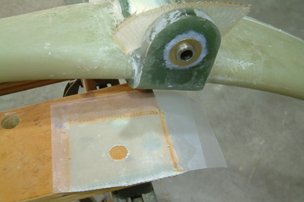
Attach
Tabs & Installation
LG Bulkhead Reinforcement
Preparing Strut
Attach Tab
Landing Gear Cover
Axles, Brakes & Brake Lines
Landing Brake
| Jig
for the Attach Tab |
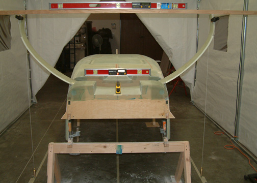
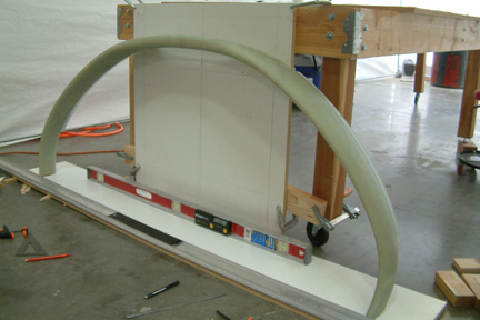 In
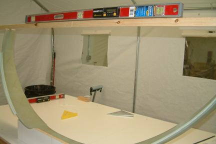
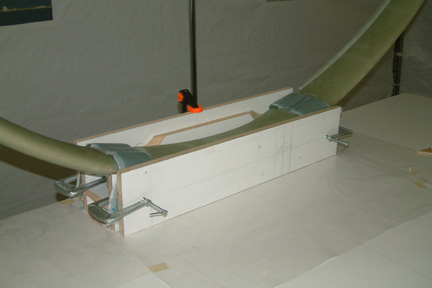
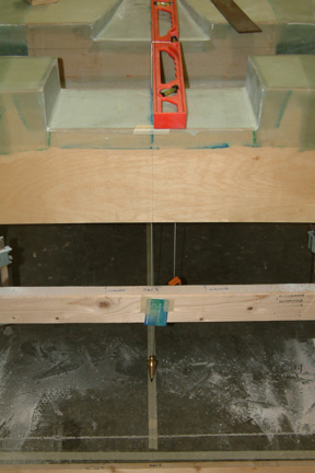
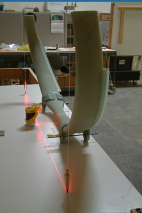
this step, I will build up two attach tabs on the main gear strut and then
install it in the fuselage between the landing gear bulkheads. However, a
precise jig is needed to support the lay up. Per plan, I lined up the strut
against a perfectly vertical backboard. Then I leveled the floor and had the
strut legs centered to 67.5" (depending
where I take the measurement. My 67.5" is at 1/4" from the front tip
of strut). I marked and set the front tips of the strut at 9.25" from back
wall and leaned the top of the strut against the backboard. I used a long straight edge
to make sure both tips are in alignment. Most importantly, I double checked all
the measurements 20 times such that they are correct. In
this step, I will build up two attach tabs on the main gear strut and then
install it in the fuselage between the landing gear bulkheads. However, a
precise jig is needed to support the lay up. Per plan, I lined up the strut
against a perfectly vertical backboard. Then I leveled the floor and had the
strut legs centered to 67.5" (depending
where I take the measurement. My 67.5" is at 1/4" from the front tip
of strut). I marked and set the front tips of the strut at 9.25" from back
wall and leaned the top of the strut against the backboard. I used a long straight edge
to make sure both tips are in alignment. Most importantly, I double checked all
the measurements 20 times such that they are correct. |
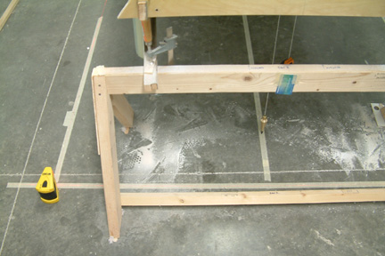
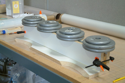 Since
I was out of pine boards, I
cut out a 3/4" x 5 1/2" particle board for the back side of the jig such that
it will fit on top of the strut and leveled at the same time. This took a lot of
patience and as I looked back later on, its well worth the effort. As shown, the
curvatures were carved out to fit against the back side of the main gear strut. Then
I laid the backboard on a flat surface and glued down the cross members with
weights as shown. I clamped a couple boards in between to keep the cross
members flat and parallel. Since
I was out of pine boards, I
cut out a 3/4" x 5 1/2" particle board for the back side of the jig such that
it will fit on top of the strut and leveled at the same time. This took a lot of
patience and as I looked back later on, its well worth the effort. As shown, the
curvatures were carved out to fit against the back side of the main gear strut. Then
I laid the backboard on a flat surface and glued down the cross members with
weights as shown. I clamped a couple boards in between to keep the cross
members flat and parallel. |
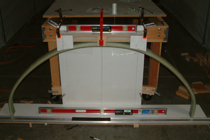
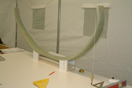
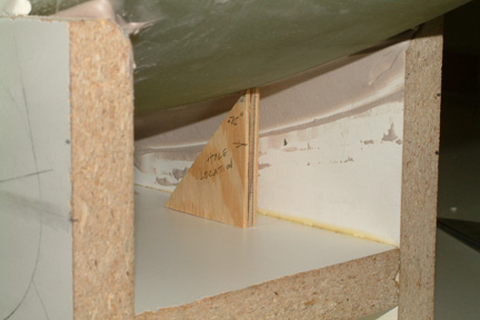
 Once
cured, I mounted the partially built jig onto the strut, leveled and clamped in place with
the big red clamp at the middle - holding it at 90o side by side AND
front & back. This is temporary while I work on the 2 front faces. Once
cured, I mounted the partially built jig onto the strut, leveled and clamped in place with
the big red clamp at the middle - holding it at 90o side by side AND
front & back. This is temporary while I work on the 2 front faces. Then I carved the two (2) front faces, clamped down for trial
before glue down. Everything is squared, measurements are correct and
looks good so far.... then Murphy showed up... 
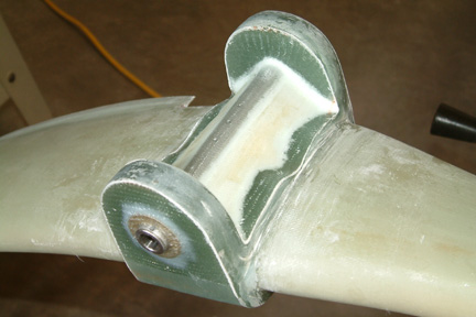
Note the base of the front faces - half of it is inside
the strut while the other half and outside the strut. The glass tab is not going to
sit smooth over the front face? Doesn't look normal to me? I must have screwed
up in some dimensions some where...
I re-checked all the instructions, re-measured every
dimension and angle - everything seemed correct. The 2 widest spots of the strut is
slightly under 5.75" located at
the center lines of the TAB positions (13" from the center, Ch 9 Fig.13).
The box is squared and leveled and there is no room for the front face to go .
Come to think of it , if the box has to be 5.75" wide
with straight edges per plan, while the edge of the strut is curved with its
widest spot at 5.75" (remember we have to remove the bulge at Ch 9, p.2, para.3?). Then how could I prevent the front face from sticking out past the strut -
other than at the widest location? Got questions and no answers ...
|
 A
late night e-mail to Wayne Hicks and a morning response followed. Basically,
don't sweat it, mine was like this too - try modeling clay, smooth it out
and here's a picture for your reference... what a great support! Made my day to
boot... With that settled, I clamped the jig in place, making sure its level
from the floor to the top of the jig, bondoed the jig onto the strut and let
cure overnight. A
late night e-mail to Wayne Hicks and a morning response followed. Basically,
don't sweat it, mine was like this too - try modeling clay, smooth it out
and here's a picture for your reference... what a great support! Made my day to
boot... With that settled, I clamped the jig in place, making sure its level
from the floor to the top of the jig, bondoed the jig onto the strut and let
cure overnight. [Hindsight] I filled all the gaps with bondo. The jig is
secured to the strut alright - it took me 6 hours to break the jig loose later
on. You may want to be a bit skimpy on the bondo stuff.]
|
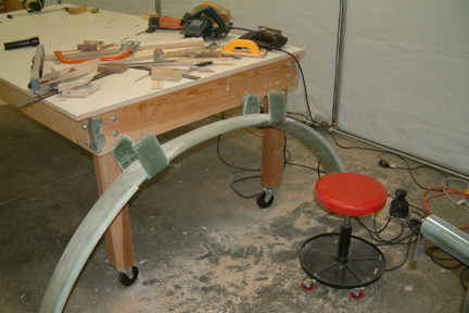
 The
next day, I made sure the work table was level. Then I transferred all the
dimensions onto the work table, removed the strut and jig off the back wall and
placed the whole assembly (with the legs up) resting on the box at the
pre-marked location. The jig lined up perfectly on the work table and the legs
were leveled at 0.0o first try! No shimming was necessary The
next day, I made sure the work table was level. Then I transferred all the
dimensions onto the work table, removed the strut and jig off the back wall and
placed the whole assembly (with the legs up) resting on the box at the
pre-marked location. The jig lined up perfectly on the work table and the legs
were leveled at 0.0o first try! No shimming was necessary  . .I was extra careful in handling the strut because I
heard all these horror stories from other builders about the strut tipping over
- grabbing their fingers with it or whacking them in the mouth on its way down.
Surprisingly, mine was quite stable and has no tipping tendency - lucky I guess.
|
 My
next task was to check the location of the leading edge relative to the
9.25" (or FS 108.25). The plumb line was right on with the right leading
edge but the left was 3/32" aft. I was really puzzled by it and pouted My
next task was to check the location of the leading edge relative to the
9.25" (or FS 108.25). The plumb line was right on with the right leading
edge but the left was 3/32" aft. I was really puzzled by it and pouted  about it over an hour before deciding to move forward. I have to compensate for it by moving the wheel axle position a bit forward
later on.
about it over an hour before deciding to move forward. I have to compensate for it by moving the wheel axle position a bit forward
later on. |
 My
next step was to smooth out the transition edge between the jig and the strut
such that the glass (tab) can lay down nicely. I went to the local crafts store
and got some modeling clay that is supposed to harden in 24 hours - good enough.
Laying down the clay was a bit of a challenge right from the start... its like used
gum and it does not want to smooth out at all. I tried pressing them with
fingers, putty knife and credit cards with no success. I just couldn't make a
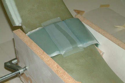
nice smooth curvature for the transition. Then ... Grandma's rolling pin My
next step was to smooth out the transition edge between the jig and the strut
such that the glass (tab) can lay down nicely. I went to the local crafts store
and got some modeling clay that is supposed to harden in 24 hours - good enough.
Laying down the clay was a bit of a challenge right from the start... its like used
gum and it does not want to smooth out at all. I tried pressing them with
fingers, putty knife and credit cards with no success. I just couldn't make a
nice smooth curvature for the transition. Then ... Grandma's rolling pin  !!! !!!
Got myself a couple sizes of wood dowels and went at it.
The modeling clay rolls over like a puppy ...and in no time the transitions
were done, nice and smooth. After it cured (in 24 hours), I took a 220 grit sand
paper and touched it up lightly - turned out great!
|
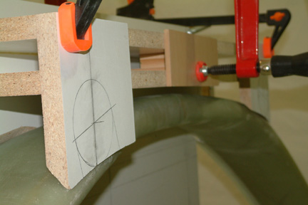
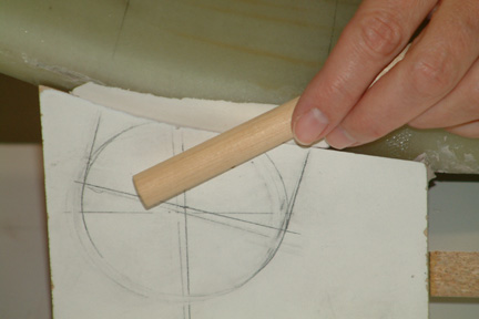
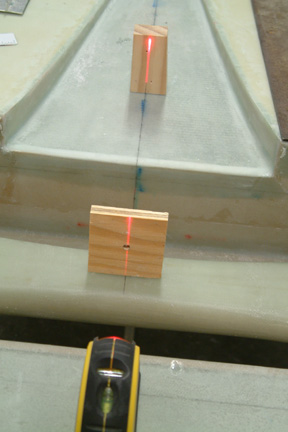
 One
of the critical dimensions was the position of the 1/4" hole on the tabs -
it has to be .75" above the highest point on the strut AT the 13"
mark. I wanted to double check that dimension before glassing the tab. At this
point, the hole location is somewhat difficult to reach with any form of
measuring device. One
of the critical dimensions was the position of the 1/4" hole on the tabs -
it has to be .75" above the highest point on the strut AT the 13"
mark. I wanted to double check that dimension before glassing the tab. At this
point, the hole location is somewhat difficult to reach with any form of
measuring device.I measured the height of the 1/4" hole above the floor of the cross member (white surface), in my case it is 1 1/4".
Then I added .75" to that, making it exactly 2". I cut up a
small triangle (as shown) with that total height (2"). Then I measured and marked a line
at the 13" position. In this case, its the distance between the hole and the edge of the
jig. I set the triangle right on the marked line. If the tip of the triangle
touches the highest point of the strut with no gaps - you are right at .75"
per plan. Mine was right on... In other words, the 1/4" hole locations are
exactly to plan.
[After thought: Though my triangular
measuring jig looked right on, somehow, it doesn't sit right in the back of my
mind. I didn't quite trust my measurements for the 'highest point' across the
top because its too wishy-washy, and it is hard to pin point exactly where those
measurements should be taken. So after I finished with the first set of glass, I
did the measurement differently (see below).]
|
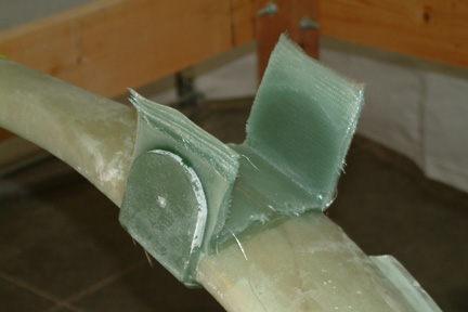
| Glassing
the Strut Tabs |
 I
cut the glass strips and prepared them per plan. The only difference was that I
cut them 3.5" wide instead of 3.8" wide because eventually I have to
cut them back down to 3" wide from tip to tip anyway. It turned out that
the glass tapes tend to slide around and by the time you got 45 layers on top of
each other, their alignment may be less than 3" of useable stack. Once I
realized that, I was real careful in lining them up including the squeezing
step. I got my 3+" without too much to spare. I
cut the glass strips and prepared them per plan. The only difference was that I
cut them 3.5" wide instead of 3.8" wide because eventually I have to
cut them back down to 3" wide from tip to tip anyway. It turned out that
the glass tapes tend to slide around and by the time you got 45 layers on top of
each other, their alignment may be less than 3" of useable stack. Once I
realized that, I was real careful in lining them up including the squeezing
step. I got my 3+" without too much to spare.
Note
I put plastic sheets AND packing tape on the table before squeezing the tabs
with clamps. [Lots of epoxy oozed out all over the place when you are not
watching...].
|
 I
also peel plied the top for a smooth transition. I
also peel plied the top for a smooth transition.
After
glassing the tabs, I proceeded to drill the two 1/4" holes using the 2x4
alignment fixture per plan. As I mentioned above, I was not comfortable with the
way the measurements were established per plan - though the two hole locations
were pretty close to level. I decided to take the longer of the 2 dimensions
from the reference point up for establishing both the 1/4" hole locations
(in this case, upwards from the top of the table surface, with the gear legs
resting on the jig up side down). The reason I took the longer dimension was
because locations of the holes will fall inside the .7" - .75" envelop
if it is off. Since my table was leveled to 0 degrees, the 1/4" holes were
level as well.
|
| Removing
the Jig |
At
this point of the project, I have not worked a whole lot with bondo. Concerned
about the stability of the jig and strut, I filled all the gaps with bondo. Well,
the jig stuck with the strut very well (actually too well) throughout the task.
When it came time to remove them - they would not budge at all. Eventually, I
had to
totally destroy the jig before I could get the strut loose - took me 6 hours. You
can see the mess I made in those 6 hours, the tools I used to do the damage
include hammer & chisel, hack saw, circular saw, jig saw, Fein tool, Dremel,
palm sander, sanding pads, sanding sticks and lots of @#$%&*! My poor jig,
looking as if it crossed paths with Chainsaw Leatherface, ended up in many many unrecognizable pieces. The good news was that the strut was freed
un-harmed  . .
[Hindsight]
Got an e-mail tip that if I heat up the bondo a bit first, the removal effort would have been much easier. Just don't heat it up too much that affects
the glass underneath.]
|
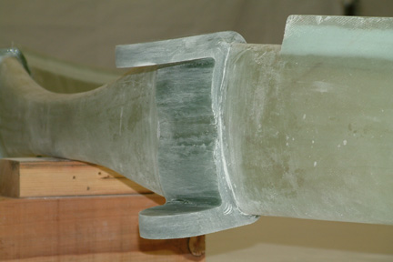
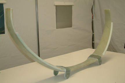 The
next step was to trim the tabs to 3" wide over the strut terminating to 1
1/2" radius ends. I first traced out the cut lines with dark marker on the
tabs. The Fein cutter is perfect for the job because I can make a straight cut
(along the cut lines) and through the 45 layers of glass without cutting into
the strut. Since the glass tab is thick and tends to get hot while its being
trimmed, I alternated the sides of a round cutter on two separate cuts at the
same time. Once the glass was cut, I smoothed out the edges and radii with a palm
sander (60 grit). Some hand sanding here and there was needed in the end. Here's
the strut standing on its trimmed tabs. There's no rocking - meaning the tabs
are accurately trimmed to the same dimensions. The
next step was to trim the tabs to 3" wide over the strut terminating to 1
1/2" radius ends. I first traced out the cut lines with dark marker on the
tabs. The Fein cutter is perfect for the job because I can make a straight cut
(along the cut lines) and through the 45 layers of glass without cutting into
the strut. Since the glass tab is thick and tends to get hot while its being
trimmed, I alternated the sides of a round cutter on two separate cuts at the
same time. Once the glass was cut, I smoothed out the edges and radii with a palm
sander (60 grit). Some hand sanding here and there was needed in the end. Here's
the strut standing on its trimmed tabs. There's no rocking - meaning the tabs
are accurately trimmed to the same dimensions. |
| Applying
Another 45 layers of Glass |
 I
laid the strut on its side and filled the 1/4" holes with wax per plan.
Then I repositioned the strut upright and filled the inside corners with
relatively dry flox. Then I brushed them lightly with pure epoxy so that it smoothed
out nicely. I then applied the 20 continuous plies of UND (#3) and then the 25
layers of BID (#4). The number of plies for UND and BID are reverse compared to
(#1 & 2) - I almost missed it. I
laid the strut on its side and filled the 1/4" holes with wax per plan.
Then I repositioned the strut upright and filled the inside corners with
relatively dry flox. Then I brushed them lightly with pure epoxy so that it smoothed
out nicely. I then applied the 20 continuous plies of UND (#3) and then the 25
layers of BID (#4). The number of plies for UND and BID are reverse compared to
(#1 & 2) - I almost missed it.
For
whatever unknown reason, my lay-ups cured much sooner than the last, so when I
was ready to clamp down and squeeze out excess epoxy - it was too late. I
performed the ritual anyway, but hardly any epoxy oozed out this time. My inside
layers turned out thicker than the outside layers - hope this is OK.
|
 Again,
I used my FEIN tool to do the tab trimming and palm sander to round them off (36
grit sand paper). As the seam line starting to get thinner, I changed the sand
paper to 100 grit and continued with the sanding until the seam between the inner
and outer layers disappeared - felt like an eternity before it came about. Again,
I used my FEIN tool to do the tab trimming and palm sander to round them off (36
grit sand paper). As the seam line starting to get thinner, I changed the sand
paper to 100 grit and continued with the sanding until the seam between the inner
and outer layers disappeared - felt like an eternity before it came about. |
| Preparing
the Fuselage for the Strut |
 I
placed the fuselage (upside down) back on the saw horse for this strut mounting
step. I made sure the fuselage was level front to back and side to side.
Recognizing that I will be taking some measurements on the floor relative to the
fuselage, I clamped the fuselage to the saw horse and bondoed the saw horse to
the floor. I then transferred the fuselage
center line onto the floor with a plumb line (as shown). I
placed the fuselage (upside down) back on the saw horse for this strut mounting
step. I made sure the fuselage was level front to back and side to side.
Recognizing that I will be taking some measurements on the floor relative to the
fuselage, I clamped the fuselage to the saw horse and bondoed the saw horse to
the floor. I then transferred the fuselage
center line onto the floor with a plumb line (as shown).
[Hindsight] I am glad I did
this because it is important that the fuselage measurement system lines up with
your floor measurement system.
|
 With a cross hair laser, I
marked the FS108.25 positions on the floor per plan. With a cross hair laser, I
marked the FS108.25 positions on the floor per plan.
I
set the strut in place on the fuselage, and tried to insert a 12" drill bit
through the forward bulkhead, strut tab and the aft bulkhead (on both sides). 3
out of the 4 holes were way off while the 4th one was slightly off. Can't
imagine I could be that far off, I spent tremendous amount of time (days) to
find the "right" position - I shimmed this and that, jigged here and
there... never got anywhere  .
I finally gave up and moved on. .
I finally gave up and moved on.
|
 I
re-established the fuselage center line with my lasers and re-drew the mounting
holes accordingly. I had to slot 2 holes and re-drill a new one per the new
measurements. I made sure the new holes were level horizontally and fore &
aft (note the bubbles on the level). After lifting the strut off... filing the holes a bit...
put strut back on...measure...
repeat..., repeat... and repeat (about 30 times), I finally got the leading edge
of both legs on target at FS108.25 except I was about 1/4" off center. I
re-established the fuselage center line with my lasers and re-drew the mounting
holes accordingly. I had to slot 2 holes and re-drill a new one per the new
measurements. I made sure the new holes were level horizontally and fore &
aft (note the bubbles on the level). After lifting the strut off... filing the holes a bit...
put strut back on...measure...
repeat..., repeat... and repeat (about 30 times), I finally got the leading edge
of both legs on target at FS108.25 except I was about 1/4" off center.
[For
the un-informed, this main gear strut is ~35 lbs and is an odd shape object (as
you can see).
Picking it up to chest high location, carrying it over to an open space, and then lowering it down to the floor level
many times is not what I consider 'a walk in the park'. After 20 some odd times, I started to wobble around like a
drunk... ] ]
Not
convinced I could be that far off AGAIN, I decided to double check my measurement
systems. Maybe the fuselage center is off relative to the floor
measurement system (remember I bondoed the saw horses to the floor?) Besides,
moving every 1/4" can be a lot of work. I need to re-check all the measurements
first. I remember Marc Zeitlin's good words - measure, measure and
measure!
|
|
 I
re-checked the center line of the strut using a combination of the plumb lines
and the cross laser. I re-measured the distance between the strut center line to
the leading edge of both legs - they are the same as expected. I also put the
12" drill bits through the tabs and made sure they were level when the
measurements were made (notice the 2 yellow bubbles resting on top of the
12" drill bits at the tabs?) I
re-checked the center line of the strut using a combination of the plumb lines
and the cross laser. I re-measured the distance between the strut center line to
the leading edge of both legs - they are the same as expected. I also put the
12" drill bits through the tabs and made sure they were level when the
measurements were made (notice the 2 yellow bubbles resting on top of the
12" drill bits at the tabs?)
|
 Then
I mounted the strut back onto the fuselage, using the 2 leveled 12" drill
bits (32 times and counting...),
I re-checked that the center line of the strut aligned with the fuselage centerline
and they did... Then
I mounted the strut back onto the fuselage, using the 2 leveled 12" drill
bits (32 times and counting...),
I re-checked that the center line of the strut aligned with the fuselage centerline
and they did...
I
doubled checked the plumb line from the fuselage center line to the floor center
line to make
sure they were aligned, and they were...
|
 Still
suspecting a discrepancy between the fuselage and floor measurement system, I
placed a straight edge across the fuselage centerline and measured its distance
from the plumb lines. They were 1/4" off, just as the floor! It was
puzzling... I concluded that it had to be my neighbors who came and switched
my Stanley measuring tape with an elastic one ! Still
suspecting a discrepancy between the fuselage and floor measurement system, I
placed a straight edge across the fuselage centerline and measured its distance
from the plumb lines. They were 1/4" off, just as the floor! It was
puzzling... I concluded that it had to be my neighbors who came and switched
my Stanley measuring tape with an elastic one !
I
decided to post the question to the Cozy Forum and see how critical the
1/4" off center is. I got 3-4 responses the next morning. What a group! -
you don't even get that kind of support for a paid service. The general consensus
was 'don't sweat it... BUT' - I knew it, there's always that killer BUT... Imagine
pedaling down the road in a tricycle with the center wheel not lined up with the
center of the two back wheels... except this time, I'll be going down the runway
at 75+mph with 1200+ lbs behind me. I don't think so Bernie, do it
right...
|
 Well,
I spent the next 3 hours moving the 4 alignment holes 1/8" to correct
for the 1/4" off center. The final out come includes: Well,
I spent the next 3 hours moving the 4 alignment holes 1/8" to correct
for the 1/4" off center. The final out come includes:-
0.0o level for the fuselage;
-
0.1o level for the struts (1/4" is acceptable per plan);
-
struts are centered;
-
left strut plumb target is right on FS108.25; and
-
right strut plumb target is 3/32" ahead of FS108.25 (or ~FS108.15).
I
think that's good enough and time to move forward! I have spent way too
much time on this 1/4" mystery (and... Susann agreed  ). ).
|
| MG-1
and MG-2 |
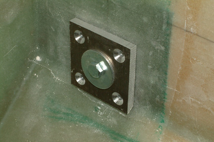 There
are the 8 metal anchor plates for supporting the struts onto the fuselage,
namely the MG-1 and MG-2. I cut them out with my band saw, put in the center
holes and counter sinks with my drill press. I used hot glue instead of
bondo to hold the plates in place before removing the 1/4" pilot rod and
the strut. I think bondo is a bit overkill and they are much more difficult to
remove compared to hot glue and you really don't need much to hold the plates
in place at this point. There
are the 8 metal anchor plates for supporting the struts onto the fuselage,
namely the MG-1 and MG-2. I cut them out with my band saw, put in the center
holes and counter sinks with my drill press. I used hot glue instead of
bondo to hold the plates in place before removing the 1/4" pilot rod and
the strut. I think bondo is a bit overkill and they are much more difficult to
remove compared to hot glue and you really don't need much to hold the plates
in place at this point.
The bottom edge of
the 2
fwd MG-2s sat
right on the bend of the forward bulkhead. Instead of cutting them shorter, I just
used the grinder and removed the lower obstructing edge as shown. I pretty much
followed the plan when installing the MG-1 and MG-2. A couple of the
S60 screws were a bit short, most likely I will have to replace them
later.
|
Landing Gear Attach Holes
Accordingly
to the plan, I am supposed to open up the MG-2 holes to 5/16". I could not
figure out the purpose for this step, because in a couple steps later, I
will have to open it up to 5/8", but I followed the plan and did it anyway.
[Hindsight: I wish I hadn't done so because I see no benefit to the step and
secondly, it eliminated an important 1/4" pilot (alignment) hole when
drilling the landing gear attach holes in the fuselage.]
I
did not flox the MG-1 & 2 at this time because I wanted to be able to check
the final position of the landing gear and be able to make minor adjustments,
if needed. Besides, I wanted to alodine the parts before
making them a permanent structure to the fuselage.
I
bought the spot facing tool from Aircraft Spruce for the next step - $38!
Before I started drilling on the real parts (i.e. the MG-1 & 2), I tried it on
a left over piece of 1/4" aluminum. This tool did not remove material as
well as any common counter bores. All it did was to generate heat and melt the
plastic caps on my C-clamps - worthless! Since I do not want to heat up the
fuselage fiberglass, I ended up blasting the MG-1 and MG-2 with compressed air
every 30 - 45 seconds throughout the entire drilling step - just to keep the
brackets and fiberglass layers from overheating. The tool got pretty dull by the time
I was done - costly tool for a single step
operation. I think you may be better off getting a counter bore w/ a
1/4" pilot for it.
| Drilling
Sequence |
 I
did not follow the plan drilling sequence per Fig. 27 because once you have
completed the forward bulkhead holes, you are left with the 1/4" pilot
holes in the aft bulkhead and MG-1 only (remember, I opened up the MG-2
to 5/16" earlier per plan?). I
did not follow the plan drilling sequence per Fig. 27 because once you have
completed the forward bulkhead holes, you are left with the 1/4" pilot
holes in the aft bulkhead and MG-1 only (remember, I opened up the MG-2
to 5/16" earlier per plan?).
Since
I opened up the MG-2 to 5/16" per plan, I cannot use them as a pilot hole
for this step. That means I must maintain both the 1/4" pilot holes in MG-1s
as long as I can. My drilling sequence was as follows:
-
drill aft MG-2 and aft bulkhead first, but stop short of going through aft MG-1;
-
drill fwd MG-1, fwd bulkhead and fwd MG-2;
-
complete drilling aft MG-1.
[Hindsight: Though
it took an extra step, as I realized later, the installation for the MG-4
bushing, the landing gear struts and MG-3 tubes were painless.]
|
| MG-4
Bushing Orientation |
|
I
misread the M9 drawing when installing the MG-4 bushings. On the right end of
the shaft, I thought it consisted of the flange of the MG-4 bushing and a washer
(though the left showed only a washer). I interpreted it to mean that the bushing goes from
the outside towards the inside. With that arrangement, my MG-3 tube will be too
short with a 3/16" gap between the end (of the MG-3 tube) and the MG-2.
Though the shaft will go through all of them, what is going to keep the
landing gear from sliding back and forth?
 Puzzled
by this, I posted the question in the Cozy Forum. I received 3 - 4 responses within
a day ranging from a graphical illustration to a phone call. What a support
group! I owe a big thank you to Wayne Hicks, Dale Rogers and Kent Ashton - who
clarified the MG-4 bushing orientation for me. They are supposed to go from the
inside toward the outside!!! Since the diameter of the MG-4 bushing has the same
diameter as the MG-3 tube, the drawing (as drawn correctly) will not have a
larger flange at the inside face of the MG-2s. Puzzled
by this, I posted the question in the Cozy Forum. I received 3 - 4 responses within
a day ranging from a graphical illustration to a phone call. What a support
group! I owe a big thank you to Wayne Hicks, Dale Rogers and Kent Ashton - who
clarified the MG-4 bushing orientation for me. They are supposed to go from the
inside toward the outside!!! Since the diameter of the MG-4 bushing has the same
diameter as the MG-3 tube, the drawing (as drawn correctly) will not have a
larger flange at the inside face of the MG-2s.
I
repositioned the bushings and to my surprise, the flanges of the bushings took out the
gap between the MG-3 tube and the MG-2s and I got a snug fit! |
 [Hindsight]
Due to the snug fit of the strut, bushing and the main landing gear, some
builders had a tough time removing the main gear later on. I took Wayne Hicks
advice and added some anti-seize (from any auto parts store) to the strut. In
addition, I ground off a slight face to one end of the strut, such that I can
turn it with a wrench if needed. [Hindsight]
Due to the snug fit of the strut, bushing and the main landing gear, some
builders had a tough time removing the main gear later on. I took Wayne Hicks
advice and added some anti-seize (from any auto parts store) to the strut. In
addition, I ground off a slight face to one end of the strut, such that I can
turn it with a wrench if needed. |
| Drilling
the Strut Tabs |
|
With
the experience of the spot face tool from Aircraft Spruce, I did not want to
spend another $38 to drill the 3/4" holes on the strut tabs. I decided to go with a hole drill
(with a 1/4" pilot) from Lowe's instead (~$9). I did a trial run with the
newly acquired hole saw on a scrap piece of lumber and found that there is
excessive play between the hole and the MG-3 tube. With the critical alignment
requirement, I preferred to have a tighter fit and not introduce additional play
at this point in the game. I decided to call it quits for the day and slept on
it - I was not happy .
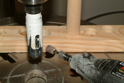 Most
hole saws have raker style teeth - i.e. some teeth point inward while others
point outward to produce a better cut. The outward teeth are the ones that
establish the overall hole diameter. I used a caliper and located the outer
most tooth - it was about .774" instead of .75", thus giving me that
unwanted clearance. With my Dremel and sanding bit, I made a few light brushes down the side of
the protruding teeth and tested the hole diameter on a scrap piece of wood.
Notice the nice fit between the 5/8" dowel and the hole in the background?
That also equates to perfect fit holes for the MG-3
tubes. Most
hole saws have raker style teeth - i.e. some teeth point inward while others
point outward to produce a better cut. The outward teeth are the ones that
establish the overall hole diameter. I used a caliper and located the outer
most tooth - it was about .774" instead of .75", thus giving me that
unwanted clearance. With my Dremel and sanding bit, I made a few light brushes down the side of
the protruding teeth and tested the hole diameter on a scrap piece of wood.
Notice the nice fit between the 5/8" dowel and the hole in the background?
That also equates to perfect fit holes for the MG-3
tubes.
I
did not follow the drill sequence of the plan (again). I drilled from the
outside towards the inside of the strut tabs, but stop short before cutting
all the way through with the first hole - thus retaining the 1/4" alignment
holes for the first end. Using both 1/4" alignment holes, I drilled through
the second tab - single shot. Then I came back to the first tab and completed
the drilling from the outside towards the inside. I ended up with a set of snug
fit holes for the MG-3s.
I
had to grind down the glass surfaces (between the tabs on top of the strut) a bit such that the MG-3 tubes
could go straight through (from hole to hole) without obstruction. Eventually,
they get covered up by foam and glass - no one will ever know...
|
Trial
Fit - The Moment of Truth Has Finally Arrived!!!
With
the MG-3 tubes fitted in the strut tabs, and the MG-4 bushings oriented correctly in
the MG-2s, I picked up the strut and placed it in position on the fuselage.
Hoping I do not have to pound the shaft through the tube with a hammer, I
thought to myself...
 |
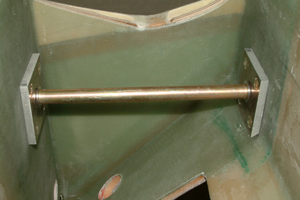
Shaft
#1 (left) slide in easily, with minor wiggling - that is good... |
|
Shaft
#2 (right) slide in with little persuasion but stops at far end of tube at MG-2.
Oh..Oh. Little pushing, lifting and shuffling, no go. Harder pushing,
lifting and shuffling - still no go. Hmmm... Back off shaft #1 out of its
far MG-2 hole. Now go back to shaft #2 and push... IT WENT THROUGH all the way!
That's more like it. Back to shaft #1, it went through all the way as well.
OK - so far so good. |
|
Checked
fuselage centerline relative to floor centerline with plumb - they stayed
aligned, good... |
|
Checked
fuselage level and it is at 0.0o - getting better... |
|
Checked
strut level and it is at 0.0o ... YES! |
|
Dropped
plumb lines from forward edge of struts and with little pushing (back and
forth), right plumb target right on FS108.25 - aaaalright! |
|
Left
plumb target at 3/32" forward of FS108.25 - well, that's good enough... |
| Both
struts are centered - Maaaaarvelous...!!! |
The
strut alignment is hereby declared good-to-go  .
.
| Glassing
the MG-3 Tube to the Strut |
|
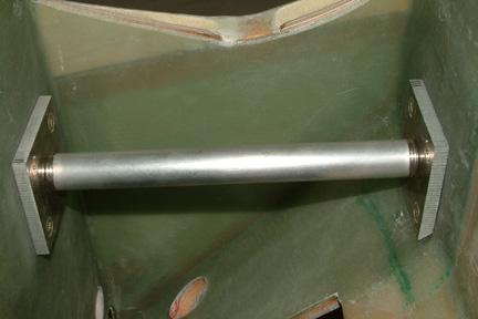
After
putting dimples onto the MG-3 tube and adding foam to the bottom of the tube, I
re-mounted the strut back onto the fuselage and double checked its positions.
While mounted, I floxed the MG-3 tube to the strut tabs and allowed to cure.
Once cured, I removed the strut (again) and added 2 layers of BID over the MG-3
tube per plan. There is not a whole lot of instructions for glassing the washer
onto the outside surfaces of the tabs. Here's what I did:
 I
first cut up 8 squares of BID (3.5" x 3.5") and made 4 2-layer squares
of BID tapes. Come to think of it, I should have made a 2-layer 7" x
7" and cut it up to 4 squares... really alert today! I
first cut up 8 squares of BID (3.5" x 3.5") and made 4 2-layer squares
of BID tapes. Come to think of it, I should have made a 2-layer 7" x
7" and cut it up to 4 squares... really alert today!
Once made, I cut a 5/8" hole in the
middle of the BID tape squares. Then I applied dry flox around the outside edges
of the 4 washers and brushed them down with pure epoxy. Next I brushed pure epoxy
on the glass mating surfaces.
|
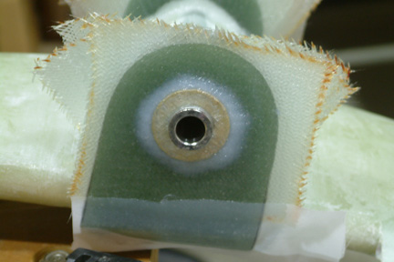 I
removed one of the plastic plies from the BID tape and slipped the glass
through the MG-3 tube onto the washer (with the second plastic ply still on the
glass). The remaining plastic ply keeps the glass from distorting, especially at
the hole location. Once I pressed down the glass onto the tab, I pulled off the second plastic ply. With a brush, I
carefully smoothed the BID over the washer and removed all the bubbles. I then
peel plied the bottom edge of the glass. I
removed one of the plastic plies from the BID tape and slipped the glass
through the MG-3 tube onto the washer (with the second plastic ply still on the
glass). The remaining plastic ply keeps the glass from distorting, especially at
the hole location. Once I pressed down the glass onto the tab, I pulled off the second plastic ply. With a brush, I
carefully smoothed the BID over the washer and removed all the bubbles. I then
peel plied the bottom edge of the glass. |
 After
cure overnight, I trimmed the excess glass around the tab and along the sides.
Glassing of the MG-3 tube onto the strut tab is complete! After
cure overnight, I trimmed the excess glass around the tab and along the sides.
Glassing of the MG-3 tube onto the strut tab is complete! |
Preparing
MG-1 for Alodine
I
waited until I was satisfied with the strut position before floxing in the aluminum brackets.
Since the alignment of the strut has been completed, I decided to disassemble
the MG-1 and MG-2, alodine and then flox them in place permanently. Since I did
not want to disturb the preset alignment (above) I first removed the strut and
hot glued all the MG-2s in place. Then I carefully removed the 4 bolts that held
the plates together and removed all the MG-1s for alodine.
Alodine
Process
I was supposed to alodine all the aluminum parts to protect them from
corrosion. I picked up both metal prep #79 and alodine #1201 form Aircraft
Spruce. I removed the metal brackets from the fuselage (one at a time) and made my first attempt.
 Since
this process required some dipping, rinsing, painting and rinsing again. I set
up a small process line and tested it out with a left over piece of aluminum. To
contain the solutions, I dropped a sandwich bag over the mixing cups for each
process step. That way the solutions are contained at all times and eventually I
can discard the used solutions in an environmentally safe way. Since
this process required some dipping, rinsing, painting and rinsing again. I set
up a small process line and tested it out with a left over piece of aluminum. To
contain the solutions, I dropped a sandwich bag over the mixing cups for each
process step. That way the solutions are contained at all times and eventually I
can discard the used solutions in an environmentally safe way.
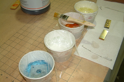
As
shown, (from left to right) - metal prep/clean, rinse #1, alodine paint station, and
rinse#2. I also made a few small hooks out of heavy duty paper clips for
handling the parts. If you look close, you can see the MG-1s in cup #1 being
cleaned.
I
found that I have to leave the parts in the metal prep station longer (about 4-5
minutes) than the instructions for better results. Probably my parts were
dirtier that normal. In addition, I only need very little alodine to cover up
the parts (and I got a gallon of it). Just hope it keeps.
All
in all, the parts turned out OK. I just wish the color shading/coverage is
more even, maybe experience will get me there someday.
|
Floxing
in MG-1
Once
the MG-1s were alodined, I painted the part with flox and bolt them back in
place, one at a time. I used the strut shafts to guide the MG-1 positions and being careful not to disturb their pre-set
positions, I also slipped the MG-4 bushings back in place and allowed to
cure.
Flox
Gremlin Strikes
Once
the MG-1s were cured, I decided to re-check the strut alignment before alodining
and floxing MG-2. The strut shaft at the pilot side slipped in as before. The
passenger side, however, would go in through the forward bulkhead, but would
butt right against the edge of the bushing at the rear bulkhead. All efforts
(other than pounding it with a hammer) failed to get the shaft passed the bushing.
With flashlight and mirror, I could see that the flat end of the shaft cleared the
bushing, however, a small fraction of the thread (at the top) would not clear the
bushing. Evidently, the Flox Gremlin came by during the night and moved my rear
MG-1 a little - just for entertainment...
As
always, troublesome parts are located at the most difficult to reach places and
this was no exception. The rear MG-1 (that needs to be re-positioned) has limited
access room. The only way to remove it is to pound it loose. However, the plate
is floxed in place with the bushing through it. I tried to pound it loose with a
hammer and screw driver at the edge & corner of the plate, hoping to 'spin'
it loose but with no avail. I pounded it hard enough to knock the
fuselage/sawhorse off its bondoed footing. Hoping to soften the flox, I heated up
the plate with a soldering iron (Susann's iron wouldn't fit) and additional
pounding - no success. I eventually ground down a screw driver tip and wedged it
in between the plate and fuselage - being careful not to scratch up the glass
surface. With patience working it up and down the edge of the plate... I finally
popped the plate off! The bushing, on the other hand, was still in tact.
Removing
the bushing was a whole different challenge. It has ~1/8" of lip at the MG-1
side and flush against MG-2. There was hardly any access room to get a hammer in
there to pound it out. Of course I tried to pull it out with pliers (at the
flange). All I ended up doing was chewing up the edge of the flange... the
bushing was staying put. I was frustrated over this for a few hours and finally,
got an idea...I used a Knock
Out Punch (reversing the punch) to pop the bushing out of the hole. Took a
bit of work, but much easier that a set of pliers!
Repositioned
and Refloxed
After
the MG-1 and MG-2 (at the passenger side) were removed, I repositioned &
refloxed them correctly - this time. The leading edge of the strut is right on
108.25" for the pilot side and 3/16" (108.4375") forward. I can
correct the 3/16" forward when installing the axle. The strut is also
centered. With the above results, I decided that its time to move on...
LG Bulkhead Reinforcement
Preparing Strut
Attach Tab
Landing Gear Cover
Axles, Brakes & Brake Lines
Landing Brake