LG Bulkhead Reinforcement Preparing Strut Attach Tab
Landing Gear Cover Axles, Brakes & Brake Lines Landing Brake
I had decided early on to install the electric landing brake, therefore, this is going to be the first moving component made on this project. I ordered Wayne Lanza's speed brake kit before I started Chapter 9 and it has been sitting on the shelf waiting for me to get to this point. Chapter 9 is a looooong chapter!
The
first step is to cut loose the landing brake with a hand-held hacksaw blade.
Since I trimmed the glass before it was fully cured in Chapter 7, I do not have
to do this step. If you didn't do that, well, have fun...![]() .
.
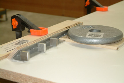
LB-19 and LB-23 are pretty straight forward. I made all the straight and 45o cuts with my table saw and the recess cut with my router. Then I cut up the 10" piano hinge, the 4 aluminum slugs and made LB-18 all in one session.
I found a minor conflict regarding the 10" piano hinge, the bill of material called for MS20001-P6 (Ch.2 p.3) while the instructions called for MS2001-P5 (Ch.9 p.9). I didn't catch it until I was trial fitting the LB-23 in the foam slot. The LB-23 hit bottom while still protruding above the fuselage on the top. Turned out P5 is about 1/4" narrower than P6. So I just trimmed down the hinge with the band saw and made to fit.
|
[Hind sight: I should have confirmed the measurement with my actuator, because 3/4" to the right will put the actuator right at the center. Now, I am 1/4" too far to the right (off center), but no harm done.]
I did not 5 min epoxy the slugs until I was able to do the first trial fit. |
I did not use the plan method to find the forward edge of the front seat back (with nails) because I already marked the location of the instrument panel, heat duct etc. on the bottom of the fuselage when I was installing the antennae. I think I was locating the landing light position such that I can route the antennae around it. I also marked the position of the instrument panel such that I can feed the antennae coax cables right up the aft face of the instrument panel. In addition, the seat back position was re-visited when I was installing the safety belt positions (Ch.8 p.2 fig.10). Per Ch.6 p.1 fig.3, the instrument panel is 19.25" and the front edge of the front seat back is 40" from F-22 respectively. Thus, front seat back is 20.75" from the instrument panel.
|
|
|
|
| Floxing LB-19 onto Landing Brake |
|
I prepared the flox and spread on the mating surfaces. Then I clamped the hinge and LB19 to the landing brake on a rigid flat surface. Left it to cure overnight. |
| Slugs Preparation |
|
|
| Micro LB-23 in Place |
|
If you look close, you can see the round hole I put in with my aggressive router (earlier). I followed Susann's advice and made a 4 ply BID disc and plugged the hole, followed with peel ply. Will see how it turns out in the morning! [Hindsight: It turned out OK the next morning.] |
Once the LB-23 is microed in place, I removed the door and prepped the foam surface. To remove the 1/8" foam throughout, I used the router, Dremel as well as muscle power. For the 45o slope along the PVC foam, I first marked the 1/8" width (of foam to be removed). Then I used a 90o router bit, set its depth and ran it along the pre-marked line. It turned out OK. Lots of dust though.
| Fitting the Electric Actuator |
|
I used CorelDraw (a graphics program) to lay out the positions of the hinge (center of small circle at bottom left) and the path of the LB-18 bracket hole (small circle @ 4" radius). Then I drew a straight line joining the hinge (center) to LB-18 path (vectors) that defines the 0o (i.e. the landing brake at closed position). Their relative positions can be found in M-13. Then I drew additional vectors indicating the landing door at 60, 70, 80 & 90 degrees (multiple line radiating from center of small circle). Then I drew out the relative location of the map pocket and profile of front seat back - the 2 sloping lines. Their dimensions can be found in M-13.
Now I drew 2 concentric circles 8.5" and 12.5" in radius (the 2 large circles) - that's the path of the actuator at fully closed and fully extended positions. I added a cross-hair at the center of the circles as well - that is the attach point (hole) at the base end of the actuator. I combined the 3 into a single object (that's a CorelDraw function). By moving the 'Object' around making sure that the small concentric circle always intersects the landing door path at 0o, then the large circle (intersecting the path) will indicate the angle of the door when the actuator is fully extended. The cross-hair will be the position for the mounting hole for the base of the actuator.
This method gives you unlimited actuator mounting positions - of course, some are better than others. I made slight modifications to the dimensions for my Cozy and determined my optimal mounting position. This worked out well for me because I did not have to hunt for my optimal mounting position under the fuselage. I was rewarded with 65o opening on my second trial. Theoretically, you can get from 0 to 90o with the 4" actuator, however, you'll be pushing against LB-18 in such a odd position, I wouldn't attempt it. In my view, I don't think you can get better than 70o practical mounting position with the 4" actuator extension. |
| Trial Fit Landing Brake |
|
I followed the plans dimension and started the actuator hole through the fuselage at 3.5" aft of the hinge center. Since I am using the electric landing brake, I did not have to cut the long slot per plan. After several trial and errors, the actuator slot ended up to be a bit under 3" from the hinge center, 2 1/4" in length, with a width of 1 3/8" at the narrow end and 1 3/4" at the wide end (to accommodate the nut and bolt).
I marked the map pocket, the actuator mounting hole location against the seat back brace, and the actuator pivot location. Then I hot glued the actuator brackets to the door and the actuator mount against the seat back brace per above calculations. I connected the actuator bolts at both ends and flipped on the switch. The door opened slowly and steadily. I was able to get a 65o max door open angle. |
| Glassing the Landing Brake Depression |
|
|
| Mounting the Actuator |
|
|
[Hindsight]
With my installation of the Vertical Power Electronic Breaker System (Chapter 22), I have to re-visit this page. Due to various reasons, my electrical system requires position feedback from the landing brake actuator. At this point, I have two choices. The first one is to replace Wayne Lanza's actuator with a new one that has a build-in position feed back. The second option is to add an external feedback to work with the system.
The sensible approach is to replace the Lanza's actuator. However, I searched all over the internet and was not able to find a feed-back actuator that has the 4" travel AND has the same physical length. The added 1 3/4" added length requires me to move the anchor point for the actuator. In addition, I have to remake the actuator cover (Chapter 24_7) to accommodate the new actuator position.
|
|
|
|
It has been discussed in the Cozy Forum that, we forgot to retract our landing brake during take off or go-around situations. This leads to over heating and much reduced climb performance. To eliminate that oversight, a sensor, installed at the full throttle location, can remedy that situation. Most builders mount a limit switch as a trigger. Due to the tight space at throttle quadrant, I need a much smaller sensor.
|
|
|
As I pushed my throttle lever forward to full power (during take off or go-around), the embedded magnet will come into close proximity of the Reed switch, which in-turn triggers the switch, resulting the retract of the landing brake. |
|
Apply flox to the back side of hinge - this is delayed, because it would be difficult to remove the landing brake once the hinge is floxed in place. [Follow up] While I was working on Chapter 16, I had the fuselage up side down again. By then, I have opened and closed the landing break many times. So... I took the opportunity and floxed in the back side of the hinge to LB23 as needed.
|
LG Bulkhead Reinforcement Preparing Strut Attach Tab
Landing Gear Cover Axles, Brakes & Brake Lines Landing Brake
 I
5 min epoxied LB-19 onto the piano hinge per plan except I moved LB-19 1" closer
to the edge. This is based on the input from various web sites.
I
5 min epoxied LB-19 onto the piano hinge per plan except I moved LB-19 1" closer
to the edge. This is based on the input from various web sites.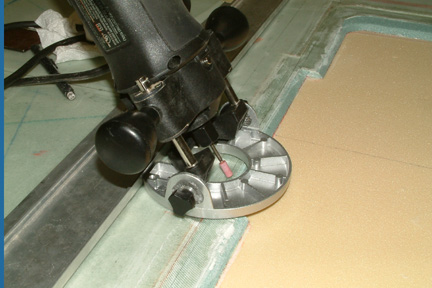 Once
the seat back position was located, I marked the foam slot position with my
cross laser. I used my Rotozip and a Dremel 1/4" grinding bit to do the
job. Normally I do not like the Rotozip because it is a bit too aggressive and
tends to take off on me if the material is non-uniform. Since I was cutting
foam, it worked well. The only problem with it this time was that I set the
angle at 30o instead of 45o. In addition, I marked the
slot position wrong. I must have been having a brain dead attack that evening
Once
the seat back position was located, I marked the foam slot position with my
cross laser. I used my Rotozip and a Dremel 1/4" grinding bit to do the
job. Normally I do not like the Rotozip because it is a bit too aggressive and
tends to take off on me if the material is non-uniform. Since I was cutting
foam, it worked well. The only problem with it this time was that I set the
angle at 30o instead of 45o. In addition, I marked the
slot position wrong. I must have been having a brain dead attack that evening 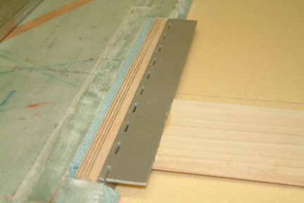 I
re-checked the slot location, reset the route angle and filled the previous (wrong)
slot with a strip of blue foam. It fit OK. Note the slugs are not in yet. I used
three layers of duct tape instead of the shim (per Cozy forum FAQ) between the
piano hinge and LB-23. It worked well.
I
re-checked the slot location, reset the route angle and filled the previous (wrong)
slot with a strip of blue foam. It fit OK. Note the slugs are not in yet. I used
three layers of duct tape instead of the shim (per Cozy forum FAQ) between the
piano hinge and LB-23. It worked well.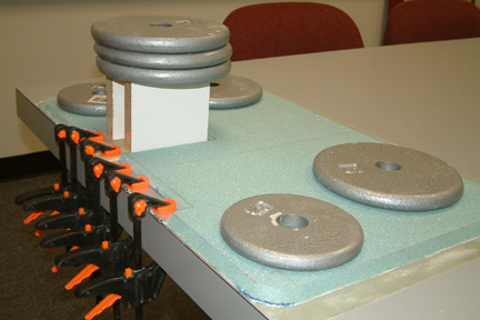 With
LB-23 & LB-19 fitted in the foam slot, I placed the landing brake on top and
performed another trial fit. This time, I marked the LB-19 position relative
to the landing brake at its desired position. Once completed, I turned the
landing brake over and routed the foam away for the piano hinge and LB-19. I was a
bit aggressive with the router when removing the foam. It put a round
hole on the glass so fast before my brain cells can find the word sh**, actually
any word... Well, that has to be fixed later!
With
LB-23 & LB-19 fitted in the foam slot, I placed the landing brake on top and
performed another trial fit. This time, I marked the LB-19 position relative
to the landing brake at its desired position. Once completed, I turned the
landing brake over and routed the foam away for the piano hinge and LB-19. I was a
bit aggressive with the router when removing the foam. It put a round
hole on the glass so fast before my brain cells can find the word sh**, actually
any word... Well, that has to be fixed later!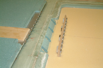 With
LB-23 position established, I 5 min epoxied the slugs to the back of LB-19 per plan. Once
cured, I marked the slug positions and carved out the foam with a razor blade.
One benefit I got with the screw up (earlier) was that the foam strip I replaced
(blue) had not been microed in yet. All I had to do was to make a cut to both
sides and the bottom of the foam strip and they came right off. I saved the foam and re-plugged
the hole after the LB-23 was installed.
With
LB-23 position established, I 5 min epoxied the slugs to the back of LB-19 per plan. Once
cured, I marked the slug positions and carved out the foam with a razor blade.
One benefit I got with the screw up (earlier) was that the foam strip I replaced
(blue) had not been microed in yet. All I had to do was to make a cut to both
sides and the bottom of the foam strip and they came right off. I saved the foam and re-plugged
the hole after the LB-23 was installed. 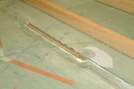 I
followed the plan closely when microing LB-23 in place. I hot glued
the two straight strips to the back of the landing brake door per plan. The
landing brake door helps to keep LB-23 in the appropriate position while the
micro cured overnight.
I
followed the plan closely when microing LB-23 in place. I hot glued
the two straight strips to the back of the landing brake door per plan. The
landing brake door helps to keep LB-23 in the appropriate position while the
micro cured overnight.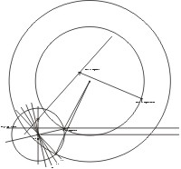 One
of the challenges with the electric landing brake is determining the mounting
position of the actuator. I wanted to mount it a position for optimal degree of
opening freedom and minimum leverage force against the pivot bolts. One of the
criteria is to keep the pivot point bolt outside the map pocket and somewhere
through the front seat brace.
One
of the challenges with the electric landing brake is determining the mounting
position of the actuator. I wanted to mount it a position for optimal degree of
opening freedom and minimum leverage force against the pivot bolts. One of the
criteria is to keep the pivot point bolt outside the map pocket and somewhere
through the front seat brace.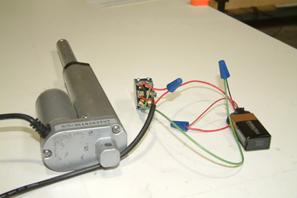 I
wired the actuator and switch per instruction and gave it some juice with a
12V power supply and 9V battery respectively - they both worked. I decided to
use the 9V battery because it moved the actuator slowly (that's good for testing)
and its just convenient.
I
wired the actuator and switch per instruction and gave it some juice with a
12V power supply and 9V battery respectively - they both worked. I decided to
use the 9V battery because it moved the actuator slowly (that's good for testing)
and its just convenient.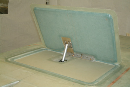 Once
I was satisfied with the trial fit, I removed the hinge, door and
actuator. Then I glassed the entire brake depression with 2 plies of BID. I added
the third ply over the LB-23 per plan. I applied the 2 ply BID separately for the
actuator depression because it would be too much of a stretch with the overall 2
ply. Actually, I was supposed to apply 3 plies there, so, I have to return and add
one more ply later.
Once
I was satisfied with the trial fit, I removed the hinge, door and
actuator. Then I glassed the entire brake depression with 2 plies of BID. I added
the third ply over the LB-23 per plan. I applied the 2 ply BID separately for the
actuator depression because it would be too much of a stretch with the overall 2
ply. Actually, I was supposed to apply 3 plies there, so, I have to return and add
one more ply later. 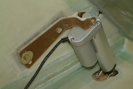 Though
the electric actuator is not called out in the plan, I added a 4-ply reinforcement strip to both sides of
the seat back brace (where the actuator bracket will be bolted to) for added
support. I drilled through the set back brace and installed the compression
tubes, bolts and washers per Wayne
Lanza's instructions.
Though
the electric actuator is not called out in the plan, I added a 4-ply reinforcement strip to both sides of
the seat back brace (where the actuator bracket will be bolted to) for added
support. I drilled through the set back brace and installed the compression
tubes, bolts and washers per Wayne
Lanza's instructions. 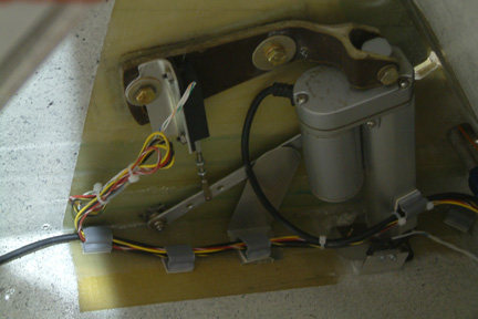 I
decided to take the second approach by adding an external feedback to the
actuator. I bought an Ray Allen (RA) -12 position sensor from Aircraft Spruce
for around $35 for this application. The challenge is that this position sensor
has 1.2" of travel, while the actuator has a 4" travel - some form of
translation is in order. I build an internal lever next to the actuator as
shown. One end of the lever arm is mounted to a bolt "anchor", glassed to the
side wall, close to the floor. You can see I mounted the RA sensor onto a small
aluminum bracket, which in turn, mount onto the rear actuator anchor bolt. The
RA sensor arm is attached to the lever arm - approximately 1 1/2" from the lever
anchor bolt.
I
decided to take the second approach by adding an external feedback to the
actuator. I bought an Ray Allen (RA) -12 position sensor from Aircraft Spruce
for around $35 for this application. The challenge is that this position sensor
has 1.2" of travel, while the actuator has a 4" travel - some form of
translation is in order. I build an internal lever next to the actuator as
shown. One end of the lever arm is mounted to a bolt "anchor", glassed to the
side wall, close to the floor. You can see I mounted the RA sensor onto a small
aluminum bracket, which in turn, mount onto the rear actuator anchor bolt. The
RA sensor arm is attached to the lever arm - approximately 1 1/2" from the lever
anchor bolt. 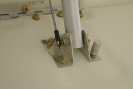 The
other end of the lever is attached to a steel rod (transfer rod) which in-turn
attached to the actuator bolt as shown. If you look closer, I drilled and tap
one end of the AN-4 bolt for attaching the rod end. Not the most elegant
installation, but functional. As the landing brake move up and down, this rod
will move up and down as well. Since the other end of the transfer rod is
attached to one end of the lever, its movement will be transferred to the
position sensor based on the position ratio between the 4" actuator travel to
the position arm travel. So far, it is functioning well.
The
other end of the lever is attached to a steel rod (transfer rod) which in-turn
attached to the actuator bolt as shown. If you look closer, I drilled and tap
one end of the AN-4 bolt for attaching the rod end. Not the most elegant
installation, but functional. As the landing brake move up and down, this rod
will move up and down as well. Since the other end of the transfer rod is
attached to one end of the lever, its movement will be transferred to the
position sensor based on the position ratio between the 4" actuator travel to
the position arm travel. So far, it is functioning well.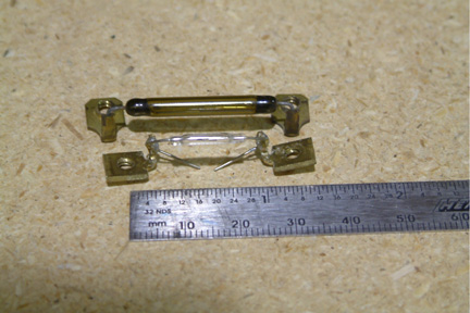 I
used a Reed Switch as a trigger sensor. These switches are commonly used in
burglar alarms systems for monitoring the opening and closing of doors. They are
small and do not require physical contact - a magnet is used to the trigger the
sensor.
I
used a Reed Switch as a trigger sensor. These switches are commonly used in
burglar alarms systems for monitoring the opening and closing of doors. They are
small and do not require physical contact - a magnet is used to the trigger the
sensor.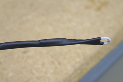 I
soldered a small wire to each end of the Reed switch and shrink wrap it as shown
- the sensor is no more than an inch in length. Then I epoxy the sensor at the
side wall of my center console, right next to the full throttle position. To
trigger the switch, I embedded a small magnet at the base of my throttle lever.
I
soldered a small wire to each end of the Reed switch and shrink wrap it as shown
- the sensor is no more than an inch in length. Then I epoxy the sensor at the
side wall of my center console, right next to the full throttle position. To
trigger the switch, I embedded a small magnet at the base of my throttle lever.