Reinforcing the Glass Strut Fabricating NG-30 Installing Worm Drive Assembly Box Assembly
Nose Floor & Sides Rudder Pedals Master Brake Cylinders Completing Nose Gear
Pitot & Static System Closing the Top Nose Door
I like the hanging rudder pedals design instead of the floor mounted style because of the following reasons:
- The left and right pedals of the floor mounted style are offset;
- I do not care for the cross bar obstructing my foot rest area, especially for the passenger.
I contacted Velocity for their standard hanging rudder pedals (the ones without toe brakes), I was quoted $500. After reviewing a PowerPoint file from Wayne Hicks (Thanks Wayne!) showing the construction and dimensions of the rudders, I feel they are way overpriced. I figured I could probably build it myself with budget left over for some improvements. The improvements were:
- replace the bushing blocks with roller bearings;
- add bearings between the inner and outer tubes;
- even out the different length of its pedal arms;
- replace the pedal steps with nicer looking ones;
- removable / replaceable pedal steps for both pilot and passenger;
- eliminate the outermost rudder cable arms (if possible).
Though the current Velocity design works perfectly fine and the above changes are NOT necessary functionally, I just figure if I have to pay $500 for it, I may as well make it look better!
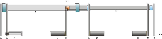
Here's the basic layout of my rudder pedals. I am using Velocity's tube inside a tube hanging pedal approach. However, I am using low profile bearings to support both inside (G) and outside (F) tubes. The rudder pedal arms (A,B,C) will be hanging from the sides instead of the middle (per Velocity) - giving a bit more leg room at the center. The foot pedals (D) will be 'bolted' to the arms, but can be removed for passenger comfort or change out to other pedal styles as needed. I figure even if the foot pedals are removed from the passenger side, the arms are still available for emergency situations. The rudder cable arms are located at the outermost ends of the tubes (F,G). I may eventually replace them with a bolt through the pedal arms (A,B) - but I'll wait till final installation to decide on this one. The pedal arms will slide over and are welded to the tubes - no holes will be drilled through the tubes. I think that will weaken the tubes tremendously (just my opinion). Lastly, the pilot's right pedal will be attached to tube (G) by means of a round plug (welded to G). The plug will have a square peg protruding from one end that pedal arm (C) will fit in and be bolted to. Since bearings and tight fittings are needed, some precision machining is expected.
I used aircraft steel tubing (4140 steel, .75" OD, 0.65" wall thickness) for my inner tube. Its the same diameter as the Velocity rudder pedals, but I am not sure what material they use. Then I used two (2) roller bearings (inner roller bearings) from McMaster Carr (.75" ID, 1" OD) to house the inner tube inside the outer tube. The roller bearings slide over the inner tubing (G) nice and snug without a problem.
| Outer Tube and Roller Bearings (F) |
|
[Hindsight:] I had to take the outer tube to a machine shop (with a lathe) and had them round off the ID (maybe shaved ~.001" off). The depth of the cut (into the tube) is the same width as the roller bearing (~.5" wide). Once shaved, the roller bearing fits into the ends of the outer tube flush and snug.
My second set of roller bearings (outer roller bearings) have an ID of 1.25" and OD of 1.5". It turned out I also had to shave ~.002" off the OD of the outer tube for the roller bearing to slip over because the tubing was not as perfectly round as the bearings.
Once assembled, I have the inner tubing sliding and spinning inside the outer tube smoothly with no slop. Similarly, the outer tube rolls smoothly inside the outer roller bearings nicely. |
| Pedal Arms |
|
I started out with 1.5"x7"x5/16" thick aircraft steel bars and drilled 1 large hole at one end to slip through the tubes. At the other end, I drilled and tapped a 1/4" hole to accommodate a threaded bolt. I also drilled 3 more holes out of the pedal arms to reduce unnecessary weight. The two arms (at the ends) are for pulling the rudder cables. I may eventually replace them with an attachment to the rudder pedals instead. I'll wait till I get to that Chapter, for now, I have them made at the same time, just in case.
The foot pedals are just 1" aluminum rods with a hole drilled through them to accommodate the center bolt. the center bolts, in turn, are screwed into the ends of the rudder pedals. |
| Pilot's Right Foot Pedal |
|
|
|
If you look closer to the picture (left), there is a set screw on the pedal arm. This set screw is not for securing the pedal arm onto the hanging rods in its final form. These set screws will be inadequate to hold the pedals in place for actual use. However, they served an important interim function. They were there for holding the pedals in place throughout its (trial & error) alignment process with the rest of the brake and rudder systems. In addition, these set screws were there to secure the rudder pedal arms in the exact position for welding. For example, when I brought my rudder assembly to the welding shop, I wanted the rudder pedal arms (pilot left & passenger left) to be firmly secured and perfectly lined up to each other + their relative position to the slot on the hanging tube (for the passenger left pedal arm), such that they can be welded exactly where I want them (refer to assembled right rudder pedal assembly picture below). |
| Rudder Pedal Parts |
|
Note
that there is a bit of precision machining was needed for making these pedals - well beyond the machining capability I have at my shop. Fortunately, I
work with many well equipped, talented, skillful small business owners who can
lend a helping hand as need arises. In this particular case, Jamie, who owns a
highly automated machine shop and provides mechanical components to aircraft
industries around the world, came to the rescue. He implemented some great
machining considerations in making this set of rudder pedal rugged and durable.
These rudder pedals can take a beating and should last a long time as well |
| Rudder Pedal Assembly |
|
|
|
To be continued... |
I waited after I completed Section 10 before mounting the rudder pedals. The plan showed the height of the foot pedal to be 7" above the fuselage floor. I found 6" is more natural to me since I am not a tall person (5'7"). I decided to set my rudder pedal height at 6". My inseam is 32" and with a 3" cushion, I found the foot pedal position fits well at 1" forward of the forward face of F-22. I confirmed those dimensions with Keith Spreuer as he is about the same height, and I rode in his plane last summer and his rudder pedal positions were quite comfortable for me. Since I lowered my rudder pedals about an inch, I was able to mount the cross tube (F) below the manual override elbow of the nose gear actuator.
I decided not to use the rudder cable arms (the outer most arms) after all because I can tie the rudder cables directly to the foot pedals. This approach has two advantages - reduced weight and more room to spread out the foot pedals.
[Hindsight] I finally got the chance to design and make the rudder cable attachments to the pedal arms. It's included in the next section (Ch13 Section 7).
| Mounting Hardware |
|
|
| Mounting the Rudder Pedals |
|
The center mounts are bolted to NG-30 sides with 2 AN4 bolts each (right below the holder) and 1 AN4 bolts through F-22 to its side (at the top). You can get a better view of this bolt from the pictures below. The side mounts are held to the steps with 2 AN4 bolts from the bottom side of the steps. |
| Right Rudder Pedal Assembly |
|
Picture left shows the assembled right rudder pedal. Note that the two mounting roller bearing assemblies are encased between the rudder pedal arms once they are welded in place (onto the hanging rod). |
|
Note that I can easily remove the foot pedals for the passenger or reduce the width of the pilot's pedals if extra foot room is really needed. |
|
|
 To
accommodate the thickness of the inner roller bearings, the outer tube has to be larger
in diameter than
the ones used by Velocity (7/8" OD). Again, I used aircraft steel tubing
(4140 steel, 1.25" OD, 1.010" ID, 0.120" wall thickness) for my outer
tube. Since the ID of the outer tube is (1.010") and the OD of the inner
bearing (1.0") - I may have to add a sleeve for a good fit. My
past experience tells me that the ID tolerance of these tubes are not that
exact, I may get lucky.
To
accommodate the thickness of the inner roller bearings, the outer tube has to be larger
in diameter than
the ones used by Velocity (7/8" OD). Again, I used aircraft steel tubing
(4140 steel, 1.25" OD, 1.010" ID, 0.120" wall thickness) for my outer
tube. Since the ID of the outer tube is (1.010") and the OD of the inner
bearing (1.0") - I may have to add a sleeve for a good fit. My
past experience tells me that the ID tolerance of these tubes are not that
exact, I may get lucky. 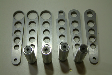 I
decided to design and make my own pedal arms instead of following the tubular
design per Velocity. In addition, I did not want to drill any holes through the pedal tubes such that the integrity of the tubes can be
preserved. This may be conservative thinking, but with all the discussions about
the twisting of the pedal tubes in the Cozy forum, I wonder if the holes may
have contributed to some of the twist. Regardless, my pedal arms, will be welded
around the tubes instead, with slight exception for the pilot's right pedal (the
one with a square hole - explain later).
I
decided to design and make my own pedal arms instead of following the tubular
design per Velocity. In addition, I did not want to drill any holes through the pedal tubes such that the integrity of the tubes can be
preserved. This may be conservative thinking, but with all the discussions about
the twisting of the pedal tubes in the Cozy forum, I wonder if the holes may
have contributed to some of the twist. Regardless, my pedal arms, will be welded
around the tubes instead, with slight exception for the pilot's right pedal (the
one with a square hole - explain later). 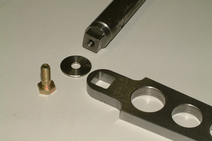 You
probably wonder how I would weld the pilot's right rudder pedal onto the inner
tube - there's just no room to do so... and you are correct! Instead of welding
the rudder pedal arm to the inner tube, I will weld a round plug into the end of
the inner tube (as shown). The external end of the round plug has a square peg
that will fit into the square hole of the rudder pedal leg. A bolt and washer
will lock the rudder pedal in place.
You
probably wonder how I would weld the pilot's right rudder pedal onto the inner
tube - there's just no room to do so... and you are correct! Instead of welding
the rudder pedal arm to the inner tube, I will weld a round plug into the end of
the inner tube (as shown). The external end of the round plug has a square peg
that will fit into the square hole of the rudder pedal leg. A bolt and washer
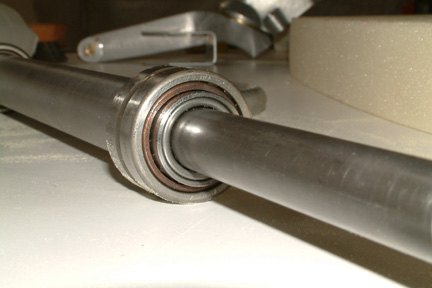
will lock the rudder pedal in place.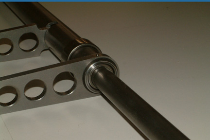 Here's
the picture of the pilot's right rudder pedal after it is assembled. You can
also see the inner and the outer roller bearings. The rudder pedal will rotate
the inner tube via the welded plug - again, no holes will be drilled through the
tube, thus maintaining the structural integrity of the tube.
Here's
the picture of the pilot's right rudder pedal after it is assembled. You can
also see the inner and the outer roller bearings. The rudder pedal will rotate
the inner tube via the welded plug - again, no holes will be drilled through the
tube, thus maintaining the structural integrity of the tube.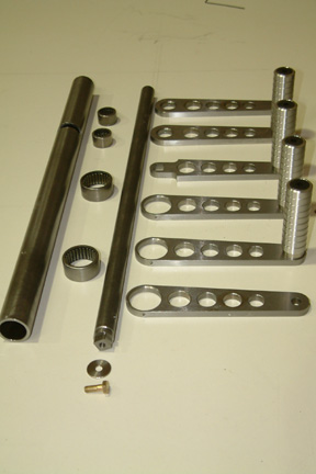 Here's
a picture that shows all the parts for the rudder pedal. I got all raw materials
and parts
from McMaster Carr. They include the steel tubings, steel plates for the rudder
pedals, roller bearings, 1" diameter aluminum rod for the foot rest, a 3/4" diameter rod
for the end plug, and the long end bolts.
Here's
a picture that shows all the parts for the rudder pedal. I got all raw materials
and parts
from McMaster Carr. They include the steel tubings, steel plates for the rudder
pedals, roller bearings, 1" diameter aluminum rod for the foot rest, a 3/4" diameter rod
for the end plug, and the long end bolts.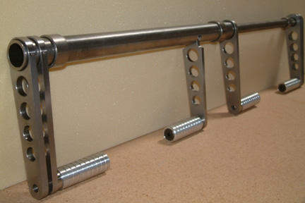 Here's
a picture of my pedal assembly. My next step is to determine the mounting
method and integrating it to the Matco master brake cylinders. I have some ideas
how to do that, but have to wait till I turn the fuselage right side up again.
Here's
a picture of my pedal assembly. My next step is to determine the mounting
method and integrating it to the Matco master brake cylinders. I have some ideas
how to do that, but have to wait till I turn the fuselage right side up again. Jamie,
the talent behind all these machining work, came to check out my installation. He
owns a highly automated machine shop with his own product lines. He provides his
products to many major aircraft companies all over the world. Jamie and I have
been working together for close to 20 years.
Jamie,
the talent behind all these machining work, came to check out my installation. He
owns a highly automated machine shop with his own product lines. He provides his
products to many major aircraft companies all over the world. Jamie and I have
been working together for close to 20 years. 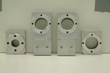 Jamie
made the roller bearing holders for the rudder pedals. It consists of 2 center,
1 left, and 1 right mounting units as shown (left). The 2 center ones will be
mounted on top of NG-30 and I shall build a small step on each side to support the end
holders.
Jamie
made the roller bearing holders for the rudder pedals. It consists of 2 center,
1 left, and 1 right mounting units as shown (left). The 2 center ones will be
mounted on top of NG-30 and I shall build a small step on each side to support the end
holders.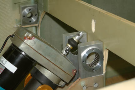 I
had to do quite a bit of shaving and shimming to get the holders seated
correctly so that the rudder pedal shaft spins freely without any binding. It
took me several hours to get it mounted to my satisfaction. The pedal tube sits
just below the manual override of the nose gear actuator (with no interference).
I
had to do quite a bit of shaving and shimming to get the holders seated
correctly so that the rudder pedal shaft spins freely without any binding. It
took me several hours to get it mounted to my satisfaction. The pedal tube sits
just below the manual override of the nose gear actuator (with no interference).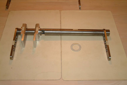 The three pedal arms (pilot left, passenger left & right)
are all welded to the hanging tubes. Attachment of the pedal arm (pilot right),
also welded, is shown in Chapter 13 Section 6. In addition, 45 degree chamfers
were cut along the circumference (both sides) of the rudder pedal arm holes, to
provide larger welding/mating surfaces for the welds to the hanging tubes.
The three pedal arms (pilot left, passenger left & right)
are all welded to the hanging tubes. Attachment of the pedal arm (pilot right),
also welded, is shown in Chapter 13 Section 6. In addition, 45 degree chamfers
were cut along the circumference (both sides) of the rudder pedal arm holes, to
provide larger welding/mating surfaces for the welds to the hanging tubes.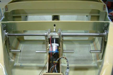 Here's
another picture of the pedals mounted in place. It looks clean...
Here's
another picture of the pedals mounted in place. It looks clean...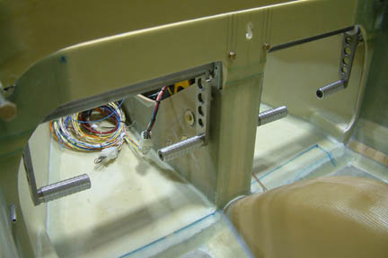 Here's
the cockpit view of the pedals.
Here's
the cockpit view of the pedals.