M-20
and Wing Root Templates
 I
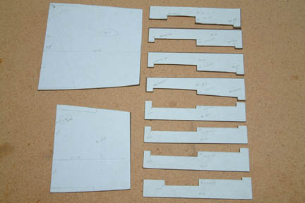
made the M-20 templates (total of 8) per plan except I added .04"
additional depth for the spar cap trough for all templates. Note the large
templates to the left - they are the wing root templates per Wayne Hicks
recommendations.
I
made the M-20 templates (total of 8) per plan except I added .04"
additional depth for the spar cap trough for all templates. Note the large
templates to the left - they are the wing root templates per Wayne Hicks
recommendations.
Here's
how I arrived at my two (2) wing root templates:
The
BL31 wing root template is from M-3 and M-24 (wing foam cut template for BL31).
I traced out the forward part of the template AND projected forward, the spar cap
troughs (both top and bottom). This gives me the total thickness of the wing
root that will match up to the trailing edge of our center section spar at BL31.
Note the upper and lower spar cap troughs has different depths. I also traced
out the WL17.4 on the template (explained later).
The
BL67.5 wing root template comes from M-23 wing cut foam template at BL67.5. I
traced out the aft part of the template all the way up to the 'shear web' cut
line, including the top and bottom corners. That's the thickness of the wing
root that will match up to the trailing edge of our spar cap at BL67.5.
Once
we know the thickness measurements of the matching wing root, all we need to
watch out for (down the road) is to make sure the matching surfaces of our
completed center section spar is slightly below or equal to (but not higher) the
wing root
surfaces.
[Hindsight]
I don't know about other builders, but when I tried to fit my template against the
lower spar cap trough after I sanded it down, I found out that the width of the
template could not fit over the center section spar. Puzzled, I measured the
distance between the template inside corners. For example, the width of the
inner corners for lower template at M-20 BL0 is 5.3". After I sanded down
CS1 Plus CS2 to 5.12", I then added CS4 (.25"), that should give me a total of
5.37". That means the template is pretty close. However, I was 5.5" -
almost 0.2" off. Don't know where I messed up. I was not able to find anything in
the archives, I decided to keep the center section spar trough at 3" and
widen the inner corner edges (mainly at CS4) to get the 5.5" width. Hope it
won't come back and bite me...you know where!
 I
prepared the CS4 pieces per plan with minor repairs. I also used a hot glue gun
and tagged a few spots along CS2 & the back wall (part D) so that it stayed
straight and flush while CS4 cures.
I
prepared the CS4 pieces per plan with minor repairs. I also used a hot glue gun
and tagged a few spots along CS2 & the back wall (part D) so that it stayed
straight and flush while CS4 cures. 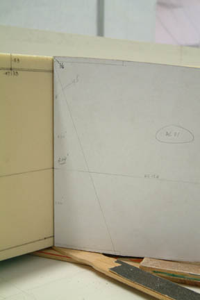 I
removed the cured spar off the fixture without much difficulty - the packing
tape kept it from sticking to the fixture. I took all the dimensions I gathered
(above) and transferred them onto the foam to guide the subsequent sanding effort.
I also marked out the BL17.4 line along the entire length of the spar. Then I butted the wing root template against
this WL17.4 at BL31 (shown left).
Note
the thickness of the wing root barely protrudes above (and below) the total
height of the center section spar. If you look closer, at
the top, there is a double line drawn on foam surface - the upper line is
the plan depth at BL31, which is .53". The lower line indicates the new
depth - recall I added .04" depth making the new depth of 0.57".
I
removed the cured spar off the fixture without much difficulty - the packing
tape kept it from sticking to the fixture. I took all the dimensions I gathered
(above) and transferred them onto the foam to guide the subsequent sanding effort.
I also marked out the BL17.4 line along the entire length of the spar. Then I butted the wing root template against
this WL17.4 at BL31 (shown left).
Note
the thickness of the wing root barely protrudes above (and below) the total
height of the center section spar. If you look closer, at
the top, there is a double line drawn on foam surface - the upper line is
the plan depth at BL31, which is .53". The lower line indicates the new
depth - recall I added .04" depth making the new depth of 0.57".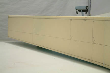 Similarly,
at the bottom, my new trough depth at BL31 is set for .42 and the spar cap
thickness is estimated to be .378 (.424 - .023*2) leaving .042 + the little bit
of space between the wing root template that is protruding above the top of the
spar.
Similarly,
at the bottom, my new trough depth at BL31 is set for .42 and the spar cap
thickness is estimated to be .378 (.424 - .023*2) leaving .042 + the little bit
of space between the wing root template that is protruding above the top of the
spar.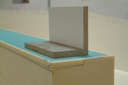 Here's
another picture of my marking on the foam at BL67.5. The upper marking is the
trough depth at the inner step and the lower marking is the trailing edge trough
depth. As other fellow builders, I also made a 90 degree sanding block for the
occasion.
Here's
another picture of my marking on the foam at BL67.5. The upper marking is the
trough depth at the inner step and the lower marking is the trailing edge trough
depth. As other fellow builders, I also made a 90 degree sanding block for the
occasion.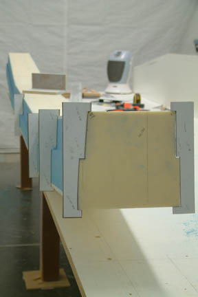 Removing
the blue foam with the angled sanding block was easy. Since it was so easy, I
got a bit careless and put another big gouge in the blue foam ...again, this
time, on the opposite side
Removing
the blue foam with the angled sanding block was easy. Since it was so easy, I
got a bit careless and put another big gouge in the blue foam ...again, this
time, on the opposite side