Chapter
17 - Section 1
Roll
Trim
In
this chapter, we will be installing the roll trim, pitch trim, landing brake,
center console, the throttle quadrant and the landing light systems. This
section relates to the roll trim system.
There
are many discussions and difference of opinions among canard builders on the
roll trim system for the Cozy. General consensus is that the roll trim system
requires little attention during flight, once it is set for passenger and/or
fuel loads, only slight adjustment is required for the remainder of flight.
Therefore, the simpler the system, the better - thus the plan's roll trim
system... However , it would
be nice to have an electric system that can be controlled by the coolie hat at
the control stick, just a flick of the switch and its set - enter the Wright
Hanka roll trim system. Both systems are not too difficult to build and I ended up
starting on both of them more or less at the same time...
, it would
be nice to have an electric system that can be controlled by the coolie hat at
the control stick, just a flick of the switch and its set - enter the Wright
Hanka roll trim system. Both systems are not too difficult to build and I ended up
starting on both of them more or less at the same time...
CZRT-1
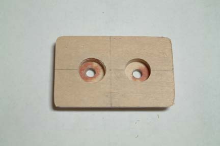 The
first task is to build a small wood block that attaches to the forward face of
the instrument panel. The function of this CZRT-1 is to secure the bolts
for holding the roll trim handle (CZRTH). Note the cavity to accommodate the
bolt heads. I also drilled through the cavity so that I can use it to line up
the block when attaching it to the forward side of the instrument panel. The
first task is to build a small wood block that attaches to the forward face of
the instrument panel. The function of this CZRT-1 is to secure the bolts
for holding the roll trim handle (CZRTH). Note the cavity to accommodate the
bolt heads. I also drilled through the cavity so that I can use it to line up
the block when attaching it to the forward side of the instrument panel.
|
|
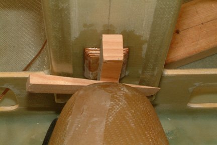
When
attaching the CZRT-1 to the instrument panel, I applied flox and 5 minute
epoxy-mix onto the mating surfaces. Then I just held it in place with a wood
block and wedge. After cure, I applied 1 layer of BID per plan. Do not forget to
round off the corners and edges for the glass to conform nicely.
|
Aligning
Tubing w/ Roll Trim Handle
Judging
the position of the roll trim handle and the CZRT-1, the CZRT-3 bulkhead is
going to be cocked. However, I went ahead and cut up the CZRT-3 per plan (Fig.1
in the plan).
As expected, it did not fit nicely. Instead of shaping it (by trial and error),
I decided to measure the mating surface first and make another one out of foam
and glass instead.
|
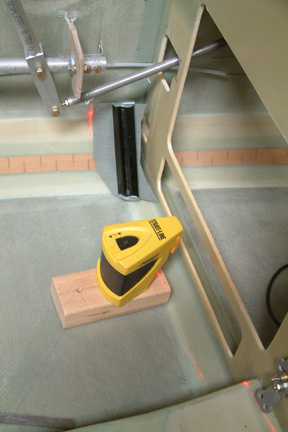
I
cast a laser beam on the fuselage connecting the roll trim handle and the torque
tube handle (CZRT-1) and pencil marked the path. Using a carpenter widget, I
traced out the profile of the mating surface along the path. I then transferred
the profile onto a 1/4" foam for the bulkhead.
|
CZRT-3
Bulkhead
 My
CZRT-3 bulkheads are made out of foam and glass instead of birch plywood per
plan. The reason for the departure was that 1) I can shape it easier (at the
mating surface) and 2) I can shape the trench to imbed the nylaflow tubing much
easier. My
CZRT-3 bulkheads are made out of foam and glass instead of birch plywood per
plan. The reason for the departure was that 1) I can shape it easier (at the
mating surface) and 2) I can shape the trench to imbed the nylaflow tubing much
easier.
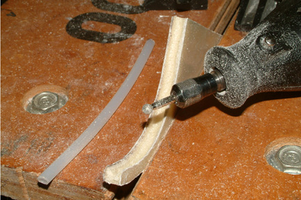
I
used a Dremel with a rounded tip tool and carved the trench between the BID
sides - much easier than birch wood.
|
|
Here's
a picture for attaching the nylaflow tubing into the trench of the bulkhead.
|
Attaching
the Roll Trim Cables and Springs
 I
did not particularly care for the plan's roll trim cable and spring arrangement as shown in Ch 17
p.2 for 3 reasons: I
did not particularly care for the plan's roll trim cable and spring arrangement as shown in Ch 17
p.2 for 3 reasons:
1)
Once the cables are installed, I cannot remove the cables between roll trim
handle and the bulkheads. It would be inconvenient to work on the seats later
on...
2)
I prefer to use nicopress instead of the two turns safety wire at the CZRT-2
location, and
3)
The spring locations will be difficult to access (for adjustment) once the arm
rests are in place.
Instead,
I reversed the cable sequence / arrangement. The spring is mounted close to the
roll trim handle under the seat - which can be accessible for adjustment at all
times. Both cable segments (of different lengths) will have a AN100-3 thimble
and nicopress at one end and a nicopress loop at the other end. The spring will
be hooked up to the nicopress loops of both cables as shown.
|
Wright
Hanka Roll Trim System
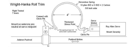 An
alternative to the plans manual system is an electric version designed by Steve
Wright and Dr. Gordon Hanka. The build plans are available in the archives as
well as Wayne Hicks web site. Though several people have successfully
fabricated and installed the system, there are limited pictures around for reference. Since the system
looks pretty simple to build, I decided to give it a try in addition to the
manual system I installed earlier. I can always abandon one of the two eventually. An
alternative to the plans manual system is an electric version designed by Steve
Wright and Dr. Gordon Hanka. The build plans are available in the archives as
well as Wayne Hicks web site. Though several people have successfully
fabricated and installed the system, there are limited pictures around for reference. Since the system
looks pretty simple to build, I decided to give it a try in addition to the
manual system I installed earlier. I can always abandon one of the two eventually.
|
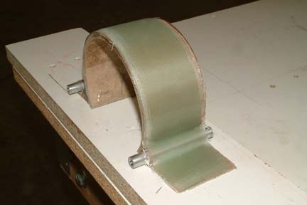
Building
the Horse-Shoe Spring
 I
made the horse-shoe spring out of 10 layers of UNI. I cut up a 2" section of
cardboard tubing (4.25" in diameter) and wrapped around it with packing
tape. I
had a bit of difficulty in determining how much of the circumference (of the
tubing) I should keep for the horse-shoe. The plans say to use about 2/3
(which should be ~240o) but the drawing shows ~270o. I
settled for the middle 255o. I
also cut a couple of 3" x 5/16" diameter aluminum tubing (to be used
for the bolt sleeves later) to help
shape the curved base of the horse-shoe spring. I applied packing tape on a flat
board and then hot glued the cardboard tubing onto it. I also drew a couple of
lines on the board - extending the edges of the horse-shoe tubing to guide the
base of the glass lay-up.
I made 10 UNI tapes and applied them on one at a time because I wanted them to
lay down nicely at the base of the horse-shoe. I also used the aluminum tubing to smooth
out the lay-up between layers. Then I peel plied and left for cure. I
made the horse-shoe spring out of 10 layers of UNI. I cut up a 2" section of
cardboard tubing (4.25" in diameter) and wrapped around it with packing
tape. I
had a bit of difficulty in determining how much of the circumference (of the
tubing) I should keep for the horse-shoe. The plans say to use about 2/3
(which should be ~240o) but the drawing shows ~270o. I
settled for the middle 255o. I
also cut a couple of 3" x 5/16" diameter aluminum tubing (to be used
for the bolt sleeves later) to help
shape the curved base of the horse-shoe spring. I applied packing tape on a flat
board and then hot glued the cardboard tubing onto it. I also drew a couple of
lines on the board - extending the edges of the horse-shoe tubing to guide the
base of the glass lay-up.
I made 10 UNI tapes and applied them on one at a time because I wanted them to
lay down nicely at the base of the horse-shoe. I also used the aluminum tubing to smooth
out the lay-up between layers. Then I peel plied and left for cure.
|
Embedding
the Bolt Sleeves
 Per
the drawing above, a couple of holes (on the horse-shoe spring) are needed for
attachment. I decided to embed a couple of bolt sleeves for the requirement. I
took the 5/16" aluminum tubes (above) and reamed them out to accommodate
an AN3 bolt. The reason for the AN3 bolt is that the Ray Allen servo arm
(discussed below) accepts the AN3 bolt. I butted one of the tubes against one
side of the arc and applied a flox radius for glassing. Six (6) layers of glass were
applied and peel plied. Per
the drawing above, a couple of holes (on the horse-shoe spring) are needed for
attachment. I decided to embed a couple of bolt sleeves for the requirement. I
took the 5/16" aluminum tubes (above) and reamed them out to accommodate
an AN3 bolt. The reason for the AN3 bolt is that the Ray Allen servo arm
(discussed below) accepts the AN3 bolt. I butted one of the tubes against one
side of the arc and applied a flox radius for glassing. Six (6) layers of glass were
applied and peel plied.
|
|
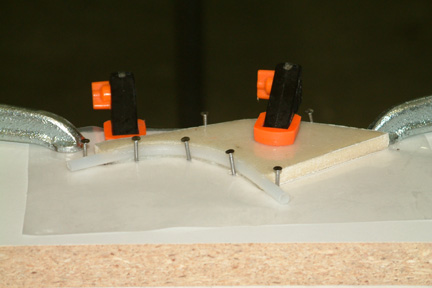
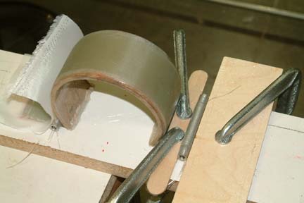 On
the other side, I placed the tube at a short distance (1 stir stick's width)
from the arc. I wrapped 3 layers of UNI under and over the top of the tube and
back. Anticipating the difficulty in keeping the UNI in place for cure, I clamped
the UNI down with stir sticks and a thin board during cure. Don't forget the packing
tapes on the boards! Once it is cured and trimmed, I plan to wrap another 3 layers of
UNI for added strength. On
the other side, I placed the tube at a short distance (1 stir stick's width)
from the arc. I wrapped 3 layers of UNI under and over the top of the tube and
back. Anticipating the difficulty in keeping the UNI in place for cure, I clamped
the UNI down with stir sticks and a thin board during cure. Don't forget the packing
tapes on the boards! Once it is cured and trimmed, I plan to wrap another 3 layers of
UNI for added strength.
|
|
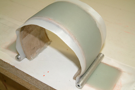
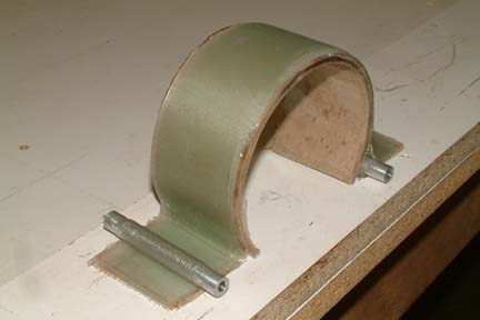 Here's
a picture after it is cured before trim... Here's
a picture after it is cured before trim...
|
|
 After
both sides were cured (actually I did both sides at the same time), I removed
peel plies and trimmed. I only trimmed one face of the horse-shoe spring to see
the result at this time. Note that I only need 5/8" of the horse-shoe (per
drawing above) and I have a couple inches worth here. All I need is to trim to
width when I am ready to install. After
both sides were cured (actually I did both sides at the same time), I removed
peel plies and trimmed. I only trimmed one face of the horse-shoe spring to see
the result at this time. Note that I only need 5/8" of the horse-shoe (per
drawing above) and I have a couple inches worth here. All I need is to trim to
width when I am ready to install.
BTW,
I plan to wrap 3 more layers of UNI around the left tube before use.
|
|
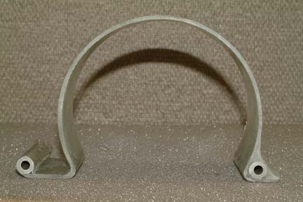
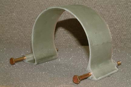 Here's
another view of the completed horse-shoe spring with AN3 bolts. The only thing
that bothers me is that it looks so thin...though I used 10 layers of UNI per
plan. Here's
another view of the completed horse-shoe spring with AN3 bolts. The only thing
that bothers me is that it looks so thin...though I used 10 layers of UNI per
plan.
|
Ray
Allen Servo
I
went to Ray Allen's web site and found the equivalent servo (T3-12A instead of the
MAC-8A per plan) - it has a 1.2" travel. Since my torque tube travel for
the aileron is 1" left and right (total of 2"), would it be too short?
I believe the original plan design and application was for the Long EZ, so I
sent a
private e-mail to Steve Wright and confirmed that '1.2" is plenty'. In
addition, 'give me a call if you have trouble installing it' - how nice I
thought...
Auto
Pilot
While
I was building the horse-shoe spring (above), I ran across the Cozy archives
referencing the need for electric roll trim and an auto-pilot. Basically, if one
intends to install an auto-pilot, an electric roll trim would be over doing a
bit. The manual roll trim system (per plan) should be adequate.
Since
I plan to install an auto-pilot (such as the Trio EZ Pilot and Altitude Hold)
and I have already installed the manual roll trim system, completing the Wright-Hanka
electric roll trim may not be necessary. It is also premature for me to
purchase any auto-pilot system at this stage of my build, I decided to put the
remaining effort (such as buying the Ray Allen Servo, etc.) on hold for now and
move on...but I'll be back!!!
|
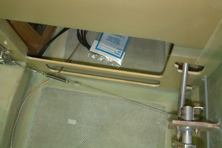
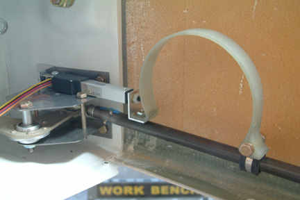 [Hindsight]
Well, I am back! While I was in Chapter 22 (Electrical Wiring), I installed the
Infinity Stick Grip. It has a coolie hat for controlling the roll and trim. I
decided to install both electric roll and trim to the stick grip. That means I
need to abandon the Plans' manual roll trim and switch over to an actuator
control roll instead. I bought a Firgelli mini-actuator and integrated to the
horse-shoe spring as shown. I used the P option for the actuator such that I can
monitor the actuator position via my Vertical Power Circuit Breaker System and
GRT EFIS. [Hindsight]
Well, I am back! While I was in Chapter 22 (Electrical Wiring), I installed the
Infinity Stick Grip. It has a coolie hat for controlling the roll and trim. I
decided to install both electric roll and trim to the stick grip. That means I
need to abandon the Plans' manual roll trim and switch over to an actuator
control roll instead. I bought a Firgelli mini-actuator and integrated to the
horse-shoe spring as shown. I used the P option for the actuator such that I can
monitor the actuator position via my Vertical Power Circuit Breaker System and
GRT EFIS.
|