Glassing in the Foam Wedges
 I
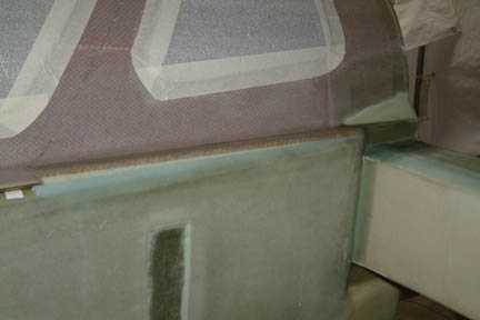
microed the foam wedges in place per plan and made up 10 6"x12" BIDs
for the engine mount reinforcement. Due to all the odd surfaces and edges at the
corners, I expected challenges in getting the BID to lay down nicely. Therefore, I
took time to smooth out all the corners and wedges with sanding and micro before
hand. In addition, I wetted out all the BIDS separately, then laid them down one
at a
time. Less challenging than expected and they turned out nicely. I peel-plied both sides and let cure overnight.
I
microed the foam wedges in place per plan and made up 10 6"x12" BIDs
for the engine mount reinforcement. Due to all the odd surfaces and edges at the
corners, I expected challenges in getting the BID to lay down nicely. Therefore, I
took time to smooth out all the corners and wedges with sanding and micro before
hand. In addition, I wetted out all the BIDS separately, then laid them down one
at a
time. Less challenging than expected and they turned out nicely. I peel-plied both sides and let cure overnight.
 [Hindsight]
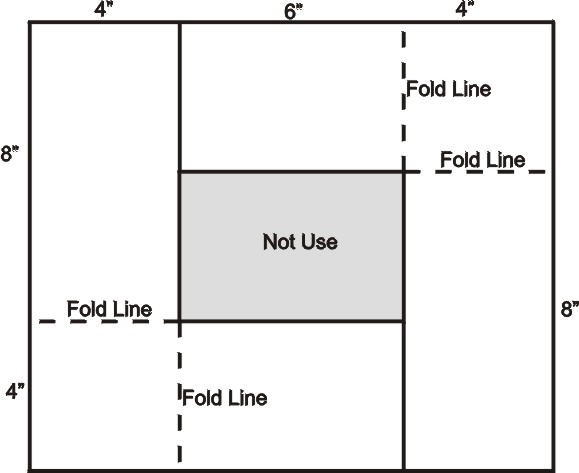
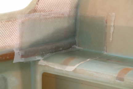
When I read the Plan instruction, I did not get the
impression that the BID should be a single continuous layer. That's why I went
with the L shape glass (above). This approach was
brought up in the Cozy forum a few days ago and it was pointed out that my
approach will have a seam (disconnect between the turtle back and the spar
surface (as show in picture left).
[Hindsight]
When I read the Plan instruction, I did not get the
impression that the BID should be a single continuous layer. That's why I went
with the L shape glass (above). This approach was
brought up in the Cozy forum a few days ago and it was pointed out that my
approach will have a seam (disconnect between the turtle back and the spar
surface (as show in picture left).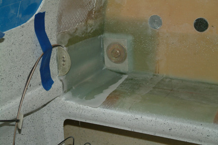
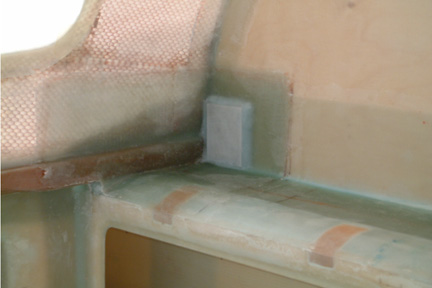 I
did not follow the plan dimensions when making the aluminum hard point because
my engine mount hard points (Chapter 4) are round discs w/ 1.75" in
diameter. I just measured the appropriate dimension such that the aluminum hard
point covers the entire disc and fits against the sides of the spar and the TB. I did not
taper
the sides of the hard points either because the tapered edges will not be useful
surfaces for bolting, thus limiting the useful size of the disc on the back
side. Instead, I just packed the sides of the aluminum inserts with flox and lay-up
the 1 ply of BID over it per plan.
I
did not follow the plan dimensions when making the aluminum hard point because
my engine mount hard points (Chapter 4) are round discs w/ 1.75" in
diameter. I just measured the appropriate dimension such that the aluminum hard
point covers the entire disc and fits against the sides of the spar and the TB. I did not
taper
the sides of the hard points either because the tapered edges will not be useful
surfaces for bolting, thus limiting the useful size of the disc on the back
side. Instead, I just packed the sides of the aluminum inserts with flox and lay-up
the 1 ply of BID over it per plan.