Chapter
18 - Section 11
Building
The Canopy Frame
Trimming
The Canopy Bottom
 The
first sentence of this section indicated that we should have at least 3/4"
of plexiglass exposed under the tape line. Evidently, it also means you trim the canopy bottom edge,
leaving 3/4" below the tape line - I sure didn't catch that one... Again, I
used my 3" high speed air cutter (Harbor Freight Model de-Thrifty, $9.99)
to do the job The
first sentence of this section indicated that we should have at least 3/4"
of plexiglass exposed under the tape line. Evidently, it also means you trim the canopy bottom edge,
leaving 3/4" below the tape line - I sure didn't catch that one... Again, I
used my 3" high speed air cutter (Harbor Freight Model de-Thrifty, $9.99)
to do the job .
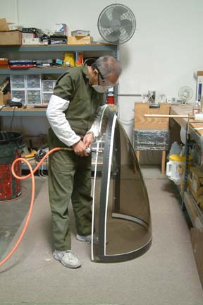
Notice I got my
full armor on because it kicks up plastic projectiles in all directions, but it makes a fast cut. I also took time to round off the inside edges
of the canopy (per Wayne Hicks' suggestion) with my palm sander for glassing down the road.
Throughout the trimming and sanding process, there were a few
times I got pretty close to dinging/scratching the canopy, I decided to take some
action... .
Notice I got my
full armor on because it kicks up plastic projectiles in all directions, but it makes a fast cut. I also took time to round off the inside edges
of the canopy (per Wayne Hicks' suggestion) with my palm sander for glassing down the road.
Throughout the trimming and sanding process, there were a few
times I got pretty close to dinging/scratching the canopy, I decided to take some
action...
|
Apply
Spray Lat - Canopy Protection
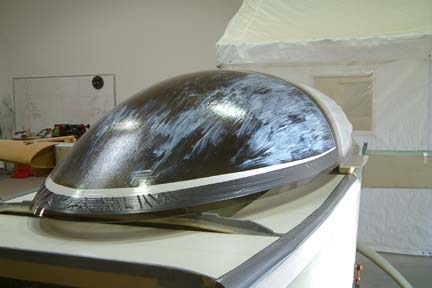 There
were many discussions in the Cozy forum on ways to protect the canopy. I have
been using the shrink wrap cover that came with the canopy. After rolling the
cover back for taping, it never wanted to
stay put. I decided to try spray lat instead. I picked up a quart from Aircraft
Spruce and tried it on a sample first. It looks like a small can of white paint. I
brushed it on and it dried within 15-20 minutes. Within an hour, it turned
clear and peels off clean. I was impressed... I brushed 3 layers on both the
outside and inside of my canopy with a SOFT brush - took me about a couple of
hours and maybe 1/4 of a quart. There
were many discussions in the Cozy forum on ways to protect the canopy. I have
been using the shrink wrap cover that came with the canopy. After rolling the
cover back for taping, it never wanted to
stay put. I decided to try spray lat instead. I picked up a quart from Aircraft
Spruce and tried it on a sample first. It looks like a small can of white paint. I
brushed it on and it dried within 15-20 minutes. Within an hour, it turned
clear and peels off clean. I was impressed... I brushed 3 layers on both the
outside and inside of my canopy with a SOFT brush - took me about a couple of
hours and maybe 1/4 of a quart.
|
Carving Out The Foam
Skirt
From what I gathered from other builders sites, carving out the foam skirt is
quite a tedious task. In addition, it is not clear if the foam/canopy interface
needs to be a perfect, good or loose fit. Instead of the 50-60 individual blocks
of foam, I decided to approach it differently...
The idea...
Based on my initial measurements, the highest point of foam/canopy interface
(tape line) is 2 11/16" above the longerons, therefore, I decided to start
with 3" thick foam blocks - bare with me here, it'll become clear as we
move on... [Hindsight]
I eventually reduced it to 2 1/4" for better visibility.
|
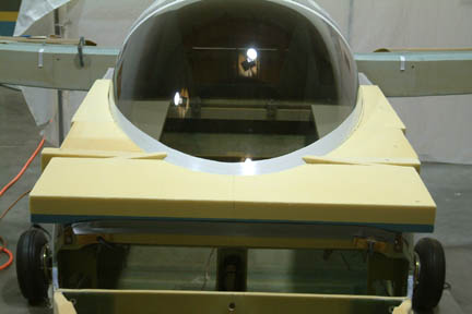
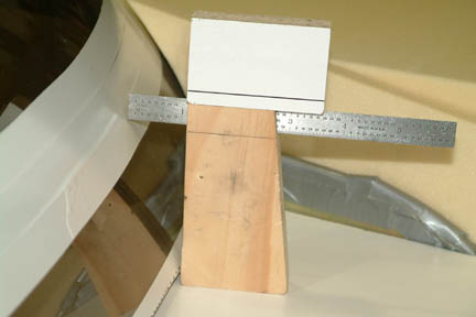 I
taped a piece of paper on top of the support boards. With the canopy in
position, I traced (projected) the base of the canopy onto the paper on the
support boards. I also made a small fixture (picture left) to hold up a ruler
such that I can measure the horizontal distance between the base (of the canopy)
and the surface of the canopy, at 3" above it. I took a measurement every 1"
along the entire perimeter of the canopy. Once I gathered all the dimensions (3"
above the support boards) , I projected them onto the paper (shown below). I
taped a piece of paper on top of the support boards. With the canopy in
position, I traced (projected) the base of the canopy onto the paper on the
support boards. I also made a small fixture (picture left) to hold up a ruler
such that I can measure the horizontal distance between the base (of the canopy)
and the surface of the canopy, at 3" above it. I took a measurement every 1"
along the entire perimeter of the canopy. Once I gathered all the dimensions (3"
above the support boards) , I projected them onto the paper (shown below).
|
|
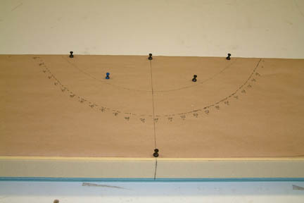 Then
I laid the paper on top of one side of the 3" foam block and traced the base
outline onto the foam with my roller wheel. Then I flipped the foam over and traced the other outline
(i.e. the 3" height outline) on the back side. Note the two colors of the
foam? One is 2" yellow and the other is 1" blue ( a total of 3"). Then
I laid the paper on top of one side of the 3" foam block and traced the base
outline onto the foam with my roller wheel. Then I flipped the foam over and traced the other outline
(i.e. the 3" height outline) on the back side. Note the two colors of the
foam? One is 2" yellow and the other is 1" blue ( a total of 3").
|
|
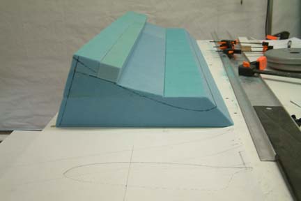
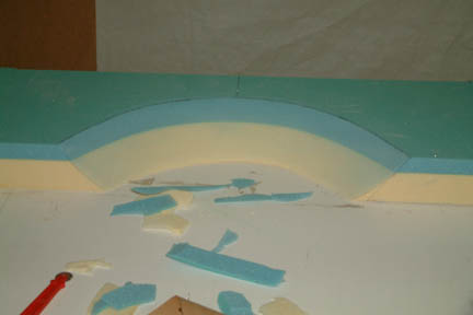 Once
completed, I carved out the foam as shown. This gives me a good starting point
in shaping the foam to the curvature of the canopy. It is much easier to shape a
few large foam pieces than 50-60 small pieces. This is a single piece I carved
out for the nose of the canopy (upside down). Once
completed, I carved out the foam as shown. This gives me a good starting point
in shaping the foam to the curvature of the canopy. It is much easier to shape a
few large foam pieces than 50-60 small pieces. This is a single piece I carved
out for the nose of the canopy (upside down).
|
Moving
Along...
I calculated
that I can make the entire foam skirt with the spare foam I have on hand, but I
have to group them into 3 foam sections - canopy front, IP slots (left
& right) and canopy sides (left & right).
|
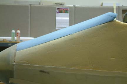
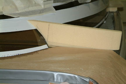 The
first foam block is the 1" thick urethane block wedged inside the wire
trough. I tackled this first just to get some feel for the idea. If the idea
doesn't work, I just throw away this small piece of foam and go back to the
plans method. On the other hand, if this works, I'll have a nice side profile to
pass onto the adjacent block. I repeated this on the right side as well. The
first foam block is the 1" thick urethane block wedged inside the wire
trough. I tackled this first just to get some feel for the idea. If the idea
doesn't work, I just throw away this small piece of foam and go back to the
plans method. On the other hand, if this works, I'll have a nice side profile to
pass onto the adjacent block. I repeated this on the right side as well.
|
|
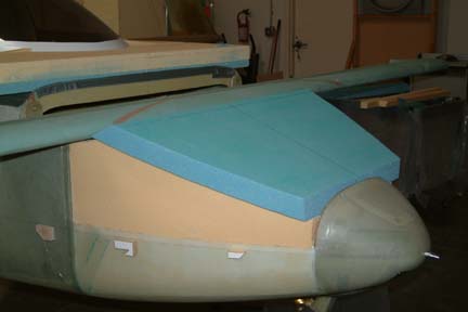
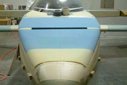
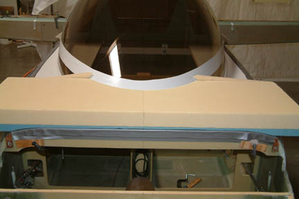 The
second set is the foam block around the front end of the canopy. Note that all
the foam is either 3" or taller. I will eventually trim them all to the
appropriate height level with the nose template I made in the previous section. The
second set is the foam block around the front end of the canopy. Note that all
the foam is either 3" or taller. I will eventually trim them all to the
appropriate height level with the nose template I made in the previous section.
|
|
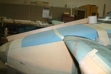
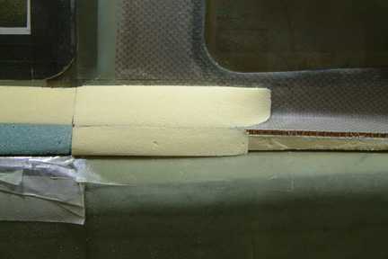
 Due
to the size of spare foam blocks I had, the canopy sides come in 3 block sets -
a 2" block right next to the IP, then a 12"x10" block and then
the long 23"x4" block set. I used the same paper templates as above
for shaping the foam blocks. Due
to the size of spare foam blocks I had, the canopy sides come in 3 block sets -
a 2" block right next to the IP, then a 12"x10" block and then
the long 23"x4" block set. I used the same paper templates as above
for shaping the foam blocks.
|
|
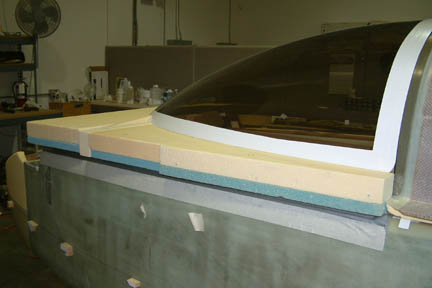
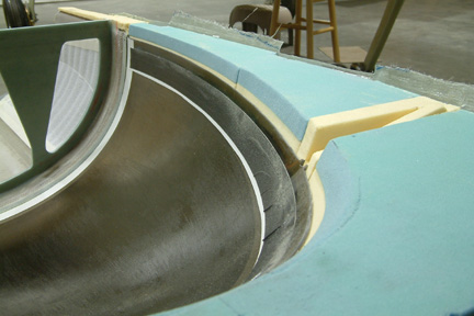
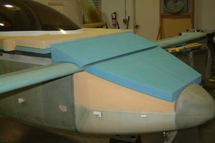
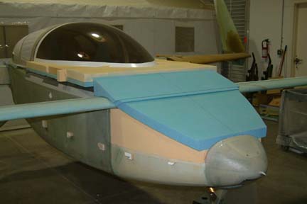
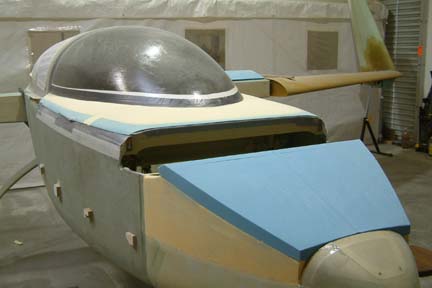
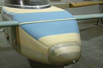
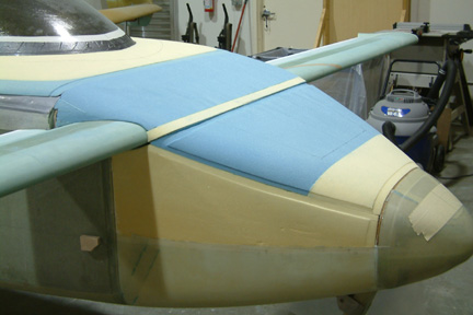
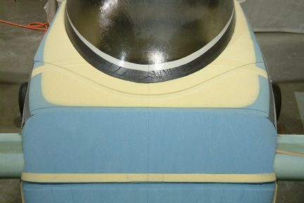
 Here's
a picture when both sides were done... Note that the top of the foam is 3"
- a bit higher than the tape line. The top of the foam will be carved to the
appropriate profile using the 2 side nose templates I made earlier. Here's
a picture when both sides were done... Note that the top of the foam is 3"
- a bit higher than the tape line. The top of the foam will be carved to the
appropriate profile using the 2 side nose templates I made earlier.
[After
Thought] This approach in cutting the foam should
save some time compared to the plans method because I am handling 9 large blocks
of foam instead of ~60 small ones. In addition, it is easier to give a nice flow
to the surface when shaping a long piece instead of many many small ones.
However, there is a draw back - it is harder to see the foam/canopy interface
between the ends (or in the middle). In addition, I won't have a joggle
underneath the bottom edge of the canopy cover. However, some builders just
remove the joggle later anyway.
|
|
 [Hindsight]
I was not certain with the outcome (with my foam carving method above) as to how
well the foam 'hugs' along the canopy - until I cut out the turtle back and flip
it open later on in this section. I was happy to see that it turned out nicely [Hindsight]
I was not certain with the outcome (with my foam carving method above) as to how
well the foam 'hugs' along the canopy - until I cut out the turtle back and flip
it open later on in this section. I was happy to see that it turned out nicely ...The
foam hugs along the canopy throughout except a slight bit of separation at the
forward tip of the canopy...I can handle that! ...The
foam hugs along the canopy throughout except a slight bit of separation at the
forward tip of the canopy...I can handle that!
|
Nose
Cover
 The nose cover
was pretty straight forward. I cut up a 2" urethane foam per plan. I have
to shape the front slope (the surface that butts against F0) so that it fits
flush. The back end was just 45o per the drawing. I have to
shave the top of the fuselage sides flat so that the nose cover can lay flush. I
was pleased to see that the flattened top of the fuselage sides have the same
height profile as the F5 opening. That means I should get a good seal to keep cold air out from the landing
gear opening and nose sides as well. The nose cover
was pretty straight forward. I cut up a 2" urethane foam per plan. I have
to shape the front slope (the surface that butts against F0) so that it fits
flush. The back end was just 45o per the drawing. I have to
shave the top of the fuselage sides flat so that the nose cover can lay flush. I
was pleased to see that the flattened top of the fuselage sides have the same
height profile as the F5 opening. That means I should get a good seal to keep cold air out from the landing
gear opening and nose sides as well.
|
Canard
Cover
The canard
cover is a bit more complicated. I have to fill the hole, where the canard
resides, so that the canard cover can be supported during the shaping process. I
had a tough time deciding which surface to carve first - the top or the bottom
(canard interface). I finally decided to carve the canard interface first
and then carve the top using the side cover templates I made in the previous
section. I hope it works!
|
 I
microed a couple blocks of foam together - enough to cover the profile of the
canard as well as clearing the top of the cover templates. I traced out the
canard profile on both sides of the foam blocks. I glued 3 pieces of 100 grit
sand paper around a long cardboard tube (from BID cloths) and removed the excess
foam. I
microed a couple blocks of foam together - enough to cover the profile of the
canard as well as clearing the top of the cover templates. I traced out the
canard profile on both sides of the foam blocks. I glued 3 pieces of 100 grit
sand paper around a long cardboard tube (from BID cloths) and removed the excess
foam.
|
|
Here's
how it turned out.
|
|
 Then
I filled the gap with a slit of foam and completed the foam preparations. Then
I filled the gap with a slit of foam and completed the foam preparations.
|
Shaping
Profile With Templates
 First,
I removed the canard. Next, I hot glued all the foam blocks back in place. Then I
mounted the pair of templates to the sides of the fuselage. I used a long
sanding block, saw blades, sanding stick and whatever I could imagine to shape
the blocks. I had to remove a lot of foam and dust flew everywhere. After a good
4 hours, I got the foam to conform to the template profile. First,
I removed the canard. Next, I hot glued all the foam blocks back in place. Then I
mounted the pair of templates to the sides of the fuselage. I used a long
sanding block, saw blades, sanding stick and whatever I could imagine to shape
the blocks. I had to remove a lot of foam and dust flew everywhere. After a good
4 hours, I got the foam to conform to the template profile.
|
Shaping
the Canopy Deck
 I
decided to start shaping the canopy deck first. I removed the templates and
started with 36 grit sanding stick, then to sanding belt (by hand), then to foam
blocks. I made the templates (at FS41, 50, 60, 70) per plan though I did not
expect to use them much because I changed the height of the tape line. However,
they turned out to be useful... I held the corresponding template at the
appropriate FS location and with a see-saw motion, I dug a trench into the foam
blocks. The trench gave me a clue as to how deep to sand...it turned out easier
than expected. Here's a work in progress picture (left). Note the sanding
blocks and the sanding belt I used for the task. I
decided to start shaping the canopy deck first. I removed the templates and
started with 36 grit sanding stick, then to sanding belt (by hand), then to foam
blocks. I made the templates (at FS41, 50, 60, 70) per plan though I did not
expect to use them much because I changed the height of the tape line. However,
they turned out to be useful... I held the corresponding template at the
appropriate FS location and with a see-saw motion, I dug a trench into the foam
blocks. The trench gave me a clue as to how deep to sand...it turned out easier
than expected. Here's a work in progress picture (left). Note the sanding
blocks and the sanding belt I used for the task.
|
|
 I
had to remove the canard foam block so that I could use the F28 profile to help
shape the front edge of the skirt. Here's a shot of the completed canopy
skirt. I
had to remove the canard foam block so that I could use the F28 profile to help
shape the front edge of the skirt. Here's a shot of the completed canopy
skirt.
|
Shaping
the Nose Cover
 I
expected the nose cover to be the easiest of the three - except I had a tough
time getting it to the shape I like. The plan suggested keeping the center of
the cover higher than its sides, which I tried. I had a difficult time to take
the same amount of foam from both sides and keep my sanding OFF the center line.
A bit more on this side, then a bit more on the other side... I ended up taking
too much foam out about 6" above the nose and resulted in a concave shape profile I
expected the nose cover to be the easiest of the three - except I had a tough
time getting it to the shape I like. The plan suggested keeping the center of
the cover higher than its sides, which I tried. I had a difficult time to take
the same amount of foam from both sides and keep my sanding OFF the center line.
A bit more on this side, then a bit more on the other side... I ended up taking
too much foam out about 6" above the nose and resulted in a concave shape profile ... ...
|
Re-Doing
the Nose Cover
 I
popped the nose cover off, including the joining strip between the nose and the
canard cover. Fortunately, there was enough urethane foam left over for another
nose cover - though I have to glue a couple of blocks together. This time I was
a lot more careful and I added a curvature board to gauge the center curvature.
I also added a tape to the center line (per Wayne Hicks suggestion) - just to
establish a "hands-off zone". The second time turned out much better. I
popped the nose cover off, including the joining strip between the nose and the
canard cover. Fortunately, there was enough urethane foam left over for another
nose cover - though I have to glue a couple of blocks together. This time I was
a lot more careful and I added a curvature board to gauge the center curvature.
I also added a tape to the center line (per Wayne Hicks suggestion) - just to
establish a "hands-off zone". The second time turned out much better.
|
Shaping
the Canard Cover
Shaping
the cover is supposed to be done in Chapter 24. Since I am shaping all 3 covers
at the same time, I have to jump ahead. Note
the small foam joining strip was added temporarily to help me visualize the
transition from canard cover to the nose cover - which is the biggest challenge
for me. Notice that slight elbow at the small yellow foam blocks? Eventually I got it to flow
better (picture below)...
|
Here's
a shot of the profile with the center line contour template. Note the sand paper
(at the front of the picture) that is taped against the canard? I used it to
shape the base of the strip (yellow) so that it sits nicely against the canard
profile.
|
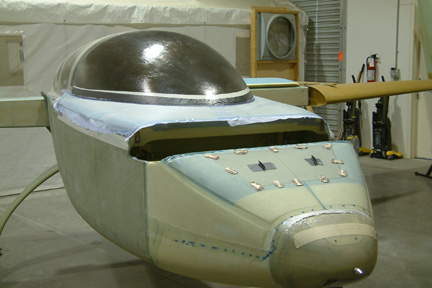
All
Three Covers Completed
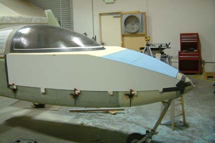
 Here's
a picture of the covers completed. Notice how
colorful my foams are - not intentional - just running out of large foam
pieces... Here's
a picture of the covers completed. Notice how
colorful my foams are - not intentional - just running out of large foam
pieces...
|
|
Here's another
shot of the completed covers and its profile. Took quite a bit of effort, but
its worth it...
|
Transition
Blocks
 I
did not do anything special with the transition blocks. I just made mine in such
a way that the glass will lay down nicely - since it will be covered up later. I
did not do anything special with the transition blocks. I just made mine in such
a way that the glass will lay down nicely - since it will be covered up later.
The
plans did not provide any direction as to the shaping of the canopy flange
forward of the cut line. It really doesn't matters much since I bought my canopy
from Featherlite and that I raised it by 1". I went ahead and trimmed the
flange as I have done on the aft half.
|
Contouring
the Forward Cut Line
I followed the
plans in contouring the forward cut line. There seems to be some confusion on
its outboard positions. I used the 4 1/2" aft F28. However, that is about
1" forward of my forward hinge - which is different from what is shown
Fig.45. I contacted a couple senior builders and theirs were the same as
mine...moving forward!
|
 I
have to scratch my head a bit in determining the 4 1/2" position from F28
(on both sides) since the fuselage is curved. Here's a picture showing how I did
it. Once I established the 4 1/2" position on one side, I used the aft edge of the canard as a 90o reference point - at
least both sides will be the same. If I remember correctly, it turned out to be
~18.5". I
have to scratch my head a bit in determining the 4 1/2" position from F28
(on both sides) since the fuselage is curved. Here's a picture showing how I did
it. Once I established the 4 1/2" position on one side, I used the aft edge of the canard as a 90o reference point - at
least both sides will be the same. If I remember correctly, it turned out to be
~18.5".
|
|
Here the top
view of the completed forward cut line plus the 1/16"x1" groove over
F28.
|
Glassing
the Canopy Deck
 I
dug a 1/4" groove along the canopy tape line per plan. As recommended by
many builders ahead of me, I made a paper template to aid me in cutting the
glass. I taped the template (half of the canopy deck) under a sheet of plastic
and then lay the BID and UNI respectively for cutting. I
dug a 1/4" groove along the canopy tape line per plan. As recommended by
many builders ahead of me, I made a paper template to aid me in cutting the
glass. I taped the template (half of the canopy deck) under a sheet of plastic
and then lay the BID and UNI respectively for cutting.
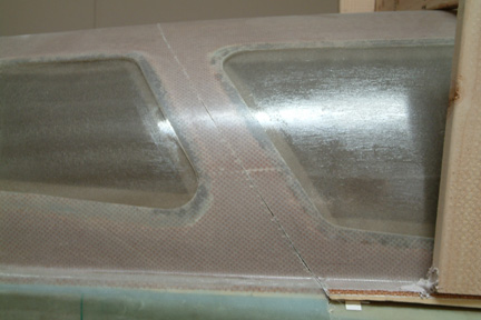
I applied micro
and glassed in the 1st layer of BID (right & left), overlapping
at the front, a couple inches off center (portside). Then I filled the groove
with dry flox somewhat up to the tape line. Right before I glassed the 2nd layer
of BID, I brushed the flox with pure epoxy, thus giving it a very smooth
surface. I shaped it a bit below the tape line. Then the 2nd layer of BID goes
on, overlapping at the front, a couple inches off center (starboard side).
|
|
 I
wet out and squeegeed both layers of UNI together between a plastic sheet and saran wrap - because they can be handled easier without falling apart. Once
wetted out, I removed the plastic sheet and lay up the UNI onto the canopy deck
while the saran wrap is still on. There is no overlap on the UNI layers, they
just meet up at the center. I
wet out and squeegeed both layers of UNI together between a plastic sheet and saran wrap - because they can be handled easier without falling apart. Once
wetted out, I removed the plastic sheet and lay up the UNI onto the canopy deck
while the saran wrap is still on. There is no overlap on the UNI layers, they
just meet up at the center.
I think the
most important step in getting a clean line is in the final peel-ply step. I
made sure the peel plies are wetted out nicely, especially at the canopy tape
line, giving it a well defined line and covering all the rough edges of the glass
underneath.
I followed
Wayne Hick's advice and extended my lay-up a bit longer down the port side
(~1") such that it will provide a better canopy seal against the longerons
down the road.
|
Building
the Support Frame
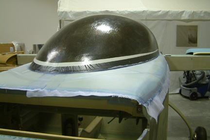
 I
decided to build the turtle back support frame before sawing through it. I just
followed Fig. 48 per plan. I used a combination of screws and bondo to hold the
support frame in place. Will see how well it holds when I tip it over. BTW, I
found it hard to keep the top of the frames even (front and back) because
the canopy deck is not even to begin with. I decided to level it afterwards. I
decided to build the turtle back support frame before sawing through it. I just
followed Fig. 48 per plan. I used a combination of screws and bondo to hold the
support frame in place. Will see how well it holds when I tip it over. BTW, I
found it hard to keep the top of the frames even (front and back) because
the canopy deck is not even to begin with. I decided to level it afterwards.
|
|
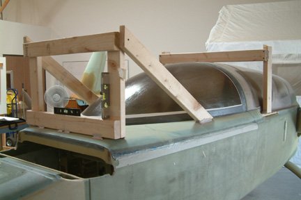
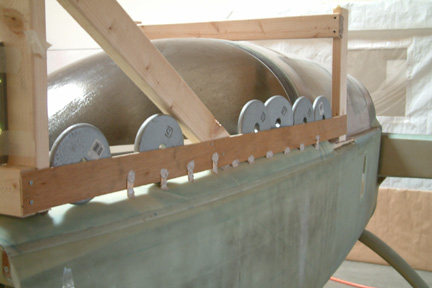 I
later learned that the frame per plan method (above) is not quite adequate. Some
builders found the canopy deck sags a bit while glassing the underside of the
canopy foam, resulting in a gap between the deck and longerons. I decided to put
the canopy back and stiffen it up a bit. I weighed the canopy deck down with ~30
lbs of weights and screwed and bondoed a cross strip as shown. I did it on both
side, of course. I
later learned that the frame per plan method (above) is not quite adequate. Some
builders found the canopy deck sags a bit while glassing the underside of the
canopy foam, resulting in a gap between the deck and longerons. I decided to put
the canopy back and stiffen it up a bit. I weighed the canopy deck down with ~30
lbs of weights and screwed and bondoed a cross strip as shown. I did it on both
side, of course.
|
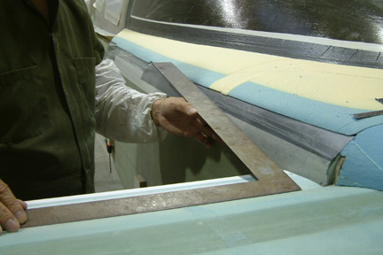
Sawing
Thru the Turtleback
 Once
the bondo cures, I took my FEIN tool and sawed through the TB along the
cut line (marked earlier). I was a bit apprehensive in taking a cut to the whole
thing but I was careful not to cut through the drip rail. Then
I used a steel blade and loosened the glass from the duct tape along the edges.
It was a bit more challenging than expected, but I got through it... Once
the bondo cures, I took my FEIN tool and sawed through the TB along the
cut line (marked earlier). I was a bit apprehensive in taking a cut to the whole
thing but I was careful not to cut through the drip rail. Then
I used a steel blade and loosened the glass from the duct tape along the edges.
It was a bit more challenging than expected, but I got through it...
|
|
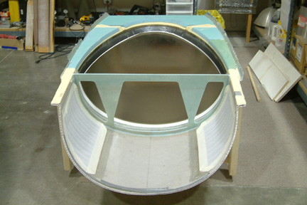 With
4 people, one at each corner, we managed to pick up the cut-out TB and
place it on the floor upside down. The fuselage, however, was a mess - ripped
tapes hanging all over the place, foam dust scattered into every crack...Took
quite a bit of work to clean them up especially removing the residue glue left
over by the duct tape. However, its good to be able to see inside the cockpit again! With
4 people, one at each corner, we managed to pick up the cut-out TB and
place it on the floor upside down. The fuselage, however, was a mess - ripped
tapes hanging all over the place, foam dust scattered into every crack...Took
quite a bit of work to clean them up especially removing the residue glue left
over by the duct tape. However, its good to be able to see inside the cockpit again!
|
|
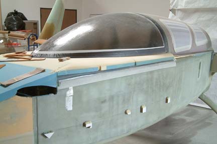
 I
removed the the
foam strip per plan, filled the honeycomb (I bought my TB from
FeatherLite) with flox and smoothed it out with epoxy. Then I added the 2 layers
of BID over the cut seam and continued over the drip rail per plan. The next day,
I trimmed off the excess glass over the drip rail and seam. Then I
smoothed out the glass to glass edge with 200 grit sand paper. It turned out
nicely! I
removed the the
foam strip per plan, filled the honeycomb (I bought my TB from
FeatherLite) with flox and smoothed it out with epoxy. Then I added the 2 layers
of BID over the cut seam and continued over the drip rail per plan. The next day,
I trimmed off the excess glass over the drip rail and seam. Then I
smoothed out the glass to glass edge with 200 grit sand paper. It turned out
nicely!
Now
I returned to Section 8 and Section 9 respectively...
|