Marking Hinge Pad Locations
 I
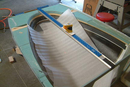
first marked the 2 - 1.6" flat surfaces along the longerons. Then I joined
the dots with a flexible aluminum strip - that was straight forward.
I
first marked the 2 - 1.6" flat surfaces along the longerons. Then I joined
the dots with a flexible aluminum strip - that was straight forward.
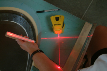
The next step was to mark the locations of the hinge pads along both sides of the longerons per Fig. 51. I set up my straight edge, T-ruler and cross-hair laser for the task (left). I made sure my T-ruler / straight edge was lined up along the center of the canopy / TB. With the cross-hair laser, I was able to determine the exact locations for the hinge and reinforcement pads along the canopy sides.
While I was fussing over the position of the straight edge, my T-ruler slipped over its side and BAM...dropped right on top of the canopy ~!@#$%^&*...~!@#$%^&*! Fortunately I had 3 layers of Spraylat on it prior. A double layer of packing material for added protection is warranted!!!
After I marked the hinge pad locations, I dug out all the foam down to the glass - creating a cavity for the subsequent step.
 To
determine the foam shaping direction, I cut up a 3/4" wide strip of wood with a
line drawn along the center. I made sure the base of the strip was exactly 90o
to its center line. By butting the base of the strip against the inside
perimeter of the canopy, I basically projected a 90o line from the
tangent of the curved surface. With a cross laser, I projected this vertical line
onto the foam, thus providing me a foam shaping direction. I repeated this
process along the entire inner perimeter of the canopy, thus plotting out the
entire shaping scheme.
To
determine the foam shaping direction, I cut up a 3/4" wide strip of wood with a
line drawn along the center. I made sure the base of the strip was exactly 90o
to its center line. By butting the base of the strip against the inside
perimeter of the canopy, I basically projected a 90o line from the
tangent of the curved surface. With a cross laser, I projected this vertical line
onto the foam, thus providing me a foam shaping direction. I repeated this
process along the entire inner perimeter of the canopy, thus plotting out the
entire shaping scheme.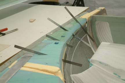 Then
I took several straight edges and 'dug' into the foam (along the shaping
directions) with one end of the straight edge sitting on top of the canopy edge,
and the other against the foam edge per Fig. 51. The straight edges show how
much foam I need to remove at each location - looks like it's quite a bit...
Then
I took several straight edges and 'dug' into the foam (along the shaping
directions) with one end of the straight edge sitting on top of the canopy edge,
and the other against the foam edge per Fig. 51. The straight edges show how
much foam I need to remove at each location - looks like it's quite a bit...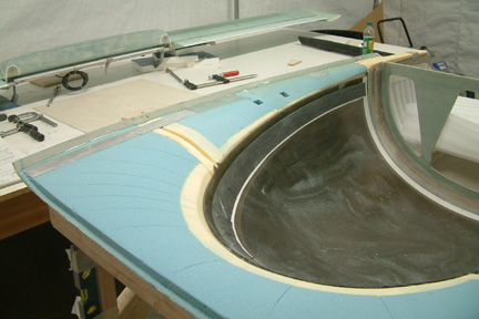 I
was a bit careful not to remove too much foam using a sanding belt. I ended up
getting a convex shape foam surface. If you look closely, you can see the
straight edge marks. Though it looked reasonably nice, it still had too much
foam left.
I
was a bit careful not to remove too much foam using a sanding belt. I ended up
getting a convex shape foam surface. If you look closely, you can see the
straight edge marks. Though it looked reasonably nice, it still had too much
foam left. 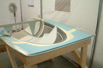 I
decided to take a more aggressive approach by using a hacksaw blade to scrape
most of the foam off. I then followed up with a foam block and 220 grit sand paper.
A lot of foam dust - but its more like it
I
decided to take a more aggressive approach by using a hacksaw blade to scrape
most of the foam off. I then followed up with a foam block and 220 grit sand paper.
A lot of foam dust - but its more like it