Chapter
19 - Section 12
Attachment,
Wing to Center Section Spar
I
purchased my wings from Dennis Oelmann and they arrived in January 2007 while I
was still building the center section spar. The timing was good because I was
able to verify the exact thickness of the wing root such that my spar mating
surface is just a hair narrower. As a result, my center section spar mating
dimension is about .2" narrower than the wing root mating surface - giving
me about .1" both on top and bottom.
Recognizing
the importance of attaching the wings to the spar correctly, I read the plans,
sifted through all available web sites and talked to several experienced builders,
so that I understood where the critical criteria are throughout the alignment
process. I picked up many good ideas from previous builders which I followed.
Here's how I approached my alignment and attachment process...
Pilot
Holes and Access Holes in the Center Section Spar
I
placed the center section spar on the work bench (forward face down) and propped
up one end with a large foam block so that the surface being drilled is
parallel (flat) to the work bench. That way, I have a much better chance of
drilling straight to the surface.
Next,
I drew the markings on the spar per plan and I was pleasantly surprised that the
pilot hole locations were right on the center line of my hard points. I started
with a short 1/8" drill bit on all pilot holes to minimize any drill
bit wobbling effect. Once completed, I opened up the holes to 1/4". I did
not lay out the same dimension on the front face of the center section spar per
plan. Instead, I continued with a 10" long 1/4" drill through the
spar, using triangles as a guide and holding the drill as steady as I could. The
pilot holes did not turn out perfect, but pretty close to dead center.
Initial
Placement of Center Section Spar
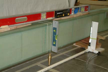 Before
matching up the center section spar and the wings, I used my cross laser and
marked (on the floor) the critical locations of the spar and wings for future
reference (Note the masking tape on the floor). For example, I drew a
horizontal line for the forward face and a perpendicular line at the center for
the spar. Then I drew perpendicular lines at BL 31, 66.3, 130.1 and 169 for the
wing placements. These dimensions assure both wings are the same distance from
the center line of the center section spar. Before
matching up the center section spar and the wings, I used my cross laser and
marked (on the floor) the critical locations of the spar and wings for future
reference (Note the masking tape on the floor). For example, I drew a
horizontal line for the forward face and a perpendicular line at the center for
the spar. Then I drew perpendicular lines at BL 31, 66.3, 130.1 and 169 for the
wing placements. These dimensions assure both wings are the same distance from
the center line of the center section spar.
I
placed the center section spar on a couple wood blocks along the aforementioned
lines. I dropped a plumb line from the center of the spar to the pre-marked
center line. I also hot glued a bubble level onto the aft face of the spar for a quick vertical reference. With a long digital level, I shimmed the spar
level to 0 degrees.
|
Building
the Water Level System
 Many
builders had good success with the water leveling method (note Clark Canedy and
Wayne Hicks web sites) and I decided to follow. I toyed with using laser beams
and found they were less accurate (if you use lumber yard, grade lasers). In
addition, they are less effective because you can't quite measure water lines
both front and back of the wings at the same time. I
went to Home Depot and purchased five 1/2" PVC pipes, elbows, 1/2"
clear OD tubing, 1/2" barb adapters (by Toro) and pipe clamps. As shown
(left), I hot glued a wood strip to the PVC elbow to support the clear tubing
(later). The barb adapter is for attaching the clear plastic tubing onto. Many
builders had good success with the water leveling method (note Clark Canedy and
Wayne Hicks web sites) and I decided to follow. I toyed with using laser beams
and found they were less accurate (if you use lumber yard, grade lasers). In
addition, they are less effective because you can't quite measure water lines
both front and back of the wings at the same time. I
went to Home Depot and purchased five 1/2" PVC pipes, elbows, 1/2"
clear OD tubing, 1/2" barb adapters (by Toro) and pipe clamps. As shown
(left), I hot glued a wood strip to the PVC elbow to support the clear tubing
(later). The barb adapter is for attaching the clear plastic tubing onto.
|
|
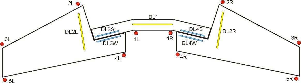
My water level system
consists of 10 vertical tubings for measuring various wing and spar heights
(i.e. 1 to 5 left & right) relative to WL17.4. In addition, I used digital
levels for spar and wing levels (DL1 to DL4). Specific measurement locations are
shown in above picture. When I was building the
spar, I marked WL17.4 along its aft face, thus 1L and 1R (above) will be my
datum point for setting WL17.4 for the entire Spar & Wing alignment
purpose. DL3 & 4, S & W (i.e. Digital level position 3 & 4 at Spar
& Wing) were added to measure the alignment between the matching surfaces of
the spar and wing root. You can find most of the alignment criteria in Chapter
19 page 10.
|
|
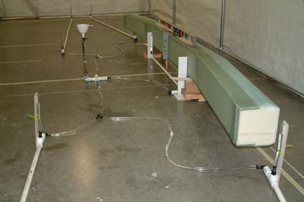 Here's
a picture of my water level system. Note the clear tubing being held upright
with tie wrap. The entire system is connected as one. Here's
a picture of my water level system. Note the clear tubing being held upright
with tie wrap. The entire system is connected as one.
The
center funnel and drain station is for filling the water to the exact WL17.4 as
needed. |
Wing
Supporting Fixtures
 Again,
this was suggested by both Wayne and Clark. To support the wings
during the alignment process, I used the bottom halves of Jig#1 and #4 (both
left and right wings). However, I have to modify them a bit so that I can
raise and lower them by turning a bolt. As shown, I added a small base board to
the jig ends by 2 small L-brackets (one on each side). Then I anchored a
12" x 1/2" bolt through the base board. At the plan jig locations, I
hot glued them directly onto the bottom of the wings. Later on, I hot glued a
couple cross member (boards) at the middle of the jigs to keep them from
wobbling. They worked well. Again,
this was suggested by both Wayne and Clark. To support the wings
during the alignment process, I used the bottom halves of Jig#1 and #4 (both
left and right wings). However, I have to modify them a bit so that I can
raise and lower them by turning a bolt. As shown, I added a small base board to
the jig ends by 2 small L-brackets (one on each side). Then I anchored a
12" x 1/2" bolt through the base board. At the plan jig locations, I
hot glued them directly onto the bottom of the wings. Later on, I hot glued a
couple cross member (boards) at the middle of the jigs to keep them from
wobbling. They worked well.
[Hindsight]
I ended up using a wedged block of foam at the outboard end of the wing. They
both worked, but the foam seems to provide a better 3-point support for
alignment.
|
Establishing
the Water Line at Wing Leading Edge
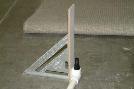
According
to the plan (Ch19 p.10), WL17.4 of the wing is tangent to the Leading Edge (LE). After I have the wings
leveled (i.e. DL2L and DL2R at 0.0o), I took a square and ran it
along the LE of the wings, marking its tangent points. I connected up the
dots - thus established my WL17.4 at the LE of the wings.
Let
the Leveling Begin...
I
first filled the water level to my pre-determined WL17.4 per the center section
spar (1L & 1R). I shimmed the center section spar to make sure its 17.4 Water Line matched
the newly filled water levels. I also placed a 4' digital level on top of the
center section spar and it was at 0.0o - Digital Level 1 position
(DL1). Turning the digital level perpendicularly against the aft face of the
spar and determined that it is at 89.9o- not
bad...
With
Susann's help, we placed the wings at their appropriate positions (per the laser
lines we drew earlier). After many hours of adjusting the bolts up and down, up
and down again, then up and down some more... we finally got the wings to seat
at plan levels as follows:
|
Left
|
Right
|
Plan
|
Comments
|
1
|
17.40
|
17.40
|
17.40
|
Datum
point on spar, spar leveled
|
2
|
17.40
|
17.40
|
17.40
|
LE
Ch19 p.10
|
3
|
17.40
|
17.40
|
17.40
|
LE
Ch19 p.10
|
4
|
17.25
|
17.40
|
17.50
|
TE
Ch19 p.10 at BL31
|
5
|
18.30
|
18.35
|
18.35
|
TE
Ch19 p.10 at BL169
|
Results
looks great, only slight variation from plan at position 4 and 5 .
The
problem, however, was the 'fit' relationship between the spar surface and the
wing root surface.
.
The
problem, however, was the 'fit' relationship between the spar surface and the
wing root surface.
| Outboard (L) |
Inboard (L) |
Spar (center) |
Inboard (R) |
Outboard (R) |
| +.04" |
+.2" |
|
+.56" |
+.0" |
+ means wing
root surface above spar surface at mating point
- means wing
root surface below spar surface at mating point
Note
the inboard wing root surface sticks up above the spar by ~.56" - way too
much to fill up later on. That means I have to raise the wing tip (on the
right) which in turn, lowers the inboard wing root. Placing a digital level at
DL4S and DL4W respectively, I raised the right wing tip slowly, until they read
the same (.6o). Then I measured the height of the LE to the WL17.4
and it measured at WL18.6 (1.2" above plan waterline!!!). I was glad to
learn from the plans, the Cozy web sites (including Nat's comments) and several
experienced builders that - dihedral is not a real critical factor as far as
flying characteristics (for the Cozy) is concerned. Its mostly aesthetic - what
a relief...
[Side
note] The
most difficult part with my alignment task was keeping the wing tips 3L & 3R at WL17.4 while
maintaining a good match between the mating surfaces (DL3 & DL4). When I
built
the spar in Chapter 14, l kept the thickness of the spar very close to the
thickness of the wing root (i.e. 0.1" above and 0.1" below). In a
sense, it gives me very little maneuvering room to keep the spar within the
thickness of the wing root matching surface. With the variances of spar and wings, it became clear to
me that I have to make a few compromises.
I
was glad that I had adequate water level measuring points that allowed me to gather
many wing/spar positions such that I can determine the best compromise... and I
made many, many, many sets (in excess of 10) of measurements...
After
wrestling with all the pros and cons from Wayne Hicks and Clark Canedy, I
followed most of their recommendations with just a slight deviation. I averaged
out the dihedral between both wings and tried to keep their positions symmetrical
while keeping the wing root/spar interface within acceptable level. As a result, here's
the alignment I ended up with:
Water
Line Measurements
|
Left
|
Right
|
Variance
(L&R) |
Plan
|
Variance
(plan) |
Comments
|
1
|
17.40
|
17.40
|
0.00 |
17.40
|
0.00 |
Expect
good fit with fuselage
|
2
|
17.40
|
17.40
|
0.00 |
17.40
|
0.00 |
Must
meet requirement
|
3
|
18.21
|
18.31
|
0.10 |
17.40
|
~0.91 |
Dihedral
at both wings but symmetrical
|
4
|
17.10
|
17.25
|
0.15 |
17.50
|
~.40 |
Most
deviations between L & R wings
|
5
|
19.03
|
19.03
|
0.00 |
18.35
|
0.68 |
Dihedral
at both wings but symmetrical
|
| Outboard (L) |
Inboard (L) |
Inboard (R) |
Outboard (R) |
| 0.0" |
+.10" |
+.25" |
0.0" |
+ means wing
root surface above spar surface at mating point
- means wing
root surface below spar surface at mating point
Digital
Level Measurements
Location
|
Angle
|
Comments
|
DL1
|
0.0
|
Center section spar is leveled
|
DL2L
|
0.0
|
Left
wing incidence (critical requirement)
|
DL2R
|
0.0
|
Right
wing incidence (critical requirement)
|
DL3S
|
0.4
|
Spar
level (left)
|
DL3W
|
0.4
|
Wing
root level (left)
|
DL4S
|
0.4
|
Spar
level (right)
|
DL4W
|
0.9
|
Wing
root level (right)
|
I
also made a measurement between the center point on the spar to the wing tips
- they both measured 181 7/8" exactly - an added symmetrical
dimension.
In
summary, the wing incidence are at 0.0o, which is a must. I will have
dihedral at both wings but they are symmetrical. The one deviation I'd rather not
have is at the inboard TE of the left wing that is .40" below plan. The
matching surfaces between the spar and wing root are all within tolerable
levels.
Drilling
the 1/4" Pilot Holes
Once
the wings were aligned, I secured them with clamps and small dabs of bondo -
bridging the hard points together. I drilled the 1/4" pilot holes through the
wing roots, using a 12" long drill bit. I drilled all the holes to the right
wing first, then the left. I drilled the inboard hole first, then the outboard
bottom, then the outboard top. As I completed each hole, I bolted the wing and
spar together with a 1/4" bolt and nut. This part was not too difficult.
However, not all the holes came out perfectly centered at the wing root hard
points, because I have to tilt the wing tips for alignment above. However, the
hole locations should clear the
bushings, bolts and nuts.
Drilling
the 5/8" Holes
After reading the Cozy
archives, I bought 3 hole saws and an adapter that accommodates a 12" pilot
drill from Grainger. I
made a test run with the hole saw on a 1/4" thick aluminum. The hole turned
out to be a bit over-sized for the 5/8" bushing. There are two obvious
contributors - protruding teeth and wobbly body. First, I brushed down the
protruding teeth with my Dremel, confirmed its diameter with my caliper and
performed a re-test. The new hole still turned out a bit over-sized.
I
took the hole saw to the belt sander and rounded off its body a bit and
performed a re-test again. This time the hole was under-sized. With my Dremel and a sanding
drum, I opened up the hole to size. This time, the bushing fits fine but the hole was a bit
out of round. I was a bit frustrated ...
...
|
 I
was talking to Gilbert (owner of a machine shop, a few units from me) regarding
the above-mentioned challenge. He said he'll give it some thought. The next day,
he returned with a funny looking tool (left). I
was talking to Gilbert (owner of a machine shop, a few units from me) regarding
the above-mentioned challenge. He said he'll give it some thought. The next day,
he returned with a funny looking tool (left).
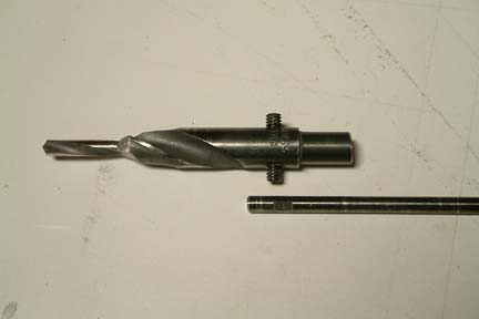
He
took a 5/8" drill bit and ground the first inch or so into a 1/4"
pilot drill. At the shaft end, he drilled a 1/4" hole with 2 set screws
such that I can slip a long 1/4" extension shaft (with 2 flat surfaces) into
it (shown left).
|
|
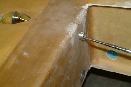
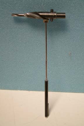 To
use the tool, I first held up the tool with a magnet and slipped it inside the spar
(through
the big hole at the bottom). Butting the shaft end against the pre-drilled
1/4" hole at the forward face of the spar, I slipped the 1/4" extension
into it. Then I pushed the tool's pilot tip into the pilot hole at the hard point.
A slight push and twist will cause the tool to 'dig' into the hard point surface
a bit, anchoring the tool in place. With an extended Allen wrench, I tightened
the two set screws in place. Grabbed onto the extension shaft with a power drill
and I was ready to start the 5/8" hole. To
use the tool, I first held up the tool with a magnet and slipped it inside the spar
(through
the big hole at the bottom). Butting the shaft end against the pre-drilled
1/4" hole at the forward face of the spar, I slipped the 1/4" extension
into it. Then I pushed the tool's pilot tip into the pilot hole at the hard point.
A slight push and twist will cause the tool to 'dig' into the hard point surface
a bit, anchoring the tool in place. With an extended Allen wrench, I tightened
the two set screws in place. Grabbed onto the extension shaft with a power drill
and I was ready to start the 5/8" hole.
|
|
 This tool allows me to use both the pre-drilled
(forward and aft) 1/4" pilot holes in the spar as a guide throughout this
drilling step. Since this is a drill bit, it generates a lot more metal shaving
compared to a hole drill. However, I do not have to be concerned with the donuts
plugging up the drill shaft. Regardless, this step took a long time - the first
hole took me an hour, because the drill was getting really hot and I had to
stop and cool everything down with my air compressor. Once I changed out to a
more powerful drill, the last hole
took me ~20 minutes. Again, once I finished one hole, I tightened a 5/8" bolt
and nut through it to keep the wing and spar in position. This tool allows me to use both the pre-drilled
(forward and aft) 1/4" pilot holes in the spar as a guide throughout this
drilling step. Since this is a drill bit, it generates a lot more metal shaving
compared to a hole drill. However, I do not have to be concerned with the donuts
plugging up the drill shaft. Regardless, this step took a long time - the first
hole took me an hour, because the drill was getting really hot and I had to
stop and cool everything down with my air compressor. Once I changed out to a
more powerful drill, the last hole
took me ~20 minutes. Again, once I finished one hole, I tightened a 5/8" bolt
and nut through it to keep the wing and spar in position.
I
can't say if this drill tool is any better than a hole saw (since I did not use
a hole saw). However, the
holes turned out nice and clean. I got a slip fit between the bushing and the hole
with NO slop. A slight nudge gets the bushings into the holes. This drill tool
is available for any fearless builder to use... just send me an e-mail and I'll send it
out to you. Bare in mind - use it at your own risk...
[Hindsight]
Use a heavy duty hand drill for this task. I ended up using a 7.8 amp DeWalt
instead of my 3.5 amp Black & Decker variable drill. The DeWalt didn't get
very hot and NO SMOKE . .
|
Shaving
the Bushing to Length
 Once
I completed the six holes, I removed the bondo and separated the spar from the
wing. The plan suggested making a small measuring tool for determining the depth
of the holes. I made one of those tools by shaping a stir stick per plan. After
transferring the first hole depth to the bushing, I got a simpler idea. Once
I completed the six holes, I removed the bondo and separated the spar from the
wing. The plan suggested making a small measuring tool for determining the depth
of the holes. I made one of those tools by shaping a stir stick per plan. After
transferring the first hole depth to the bushing, I got a simpler idea.
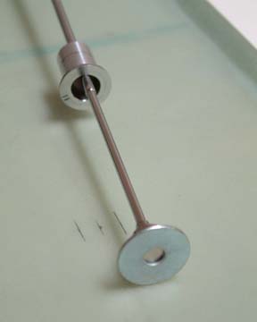
Instead
of transferring the hole depth from the tool to the bushing (using a caliper), I
assembled a collapsible magnet stick, a flat washer and the bushing as shown. I
also numbered the bushings to the holes.
|
|
 I
just 'thread' the magnet stick through the hole and, with the help of the
washer, pull the narrow end of the bushing through the hole - exposing the extra
length. I took a pencil and traced out a circular line (on the bushing) along
the hole surface. Since the plan calls for .01" shorter than hole depth, I just
grind the bushing down to and including the pencil mark. No measurement is
required and it will be exact as long as I keep track of the bushing # and hole
#. I
just 'thread' the magnet stick through the hole and, with the help of the
washer, pull the narrow end of the bushing through the hole - exposing the extra
length. I took a pencil and traced out a circular line (on the bushing) along
the hole surface. Since the plan calls for .01" shorter than hole depth, I just
grind the bushing down to and including the pencil mark. No measurement is
required and it will be exact as long as I keep track of the bushing # and hole
#.
|
|
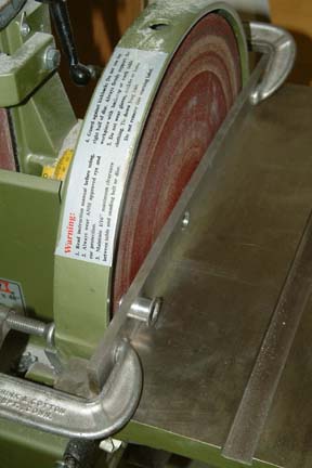 To make sure I ground
the bushing flat (90 degrees to the longitudinal axis of the bushing), I drilled
a 5/8" hole through a long piece of 1/4" aluminum strip. Then I
clamped the strip against my belt sander as shown. By slipping the bushing
through the hole and grinding it down to the pencil mark, they came out nice and
flush every time. The tough part was to hold the bushing in place while it's
getting hot by the second To make sure I ground
the bushing flat (90 degrees to the longitudinal axis of the bushing), I drilled
a 5/8" hole through a long piece of 1/4" aluminum strip. Then I
clamped the strip against my belt sander as shown. By slipping the bushing
through the hole and grinding it down to the pencil mark, they came out nice and
flush every time. The tough part was to hold the bushing in place while it's
getting hot by the second . .
After
the bushings were trimmed to length, I floxed them in place per plan. I
re-measured everything one more time to make sure nothing moved in the process.
Once confirmed, I bolted the spar to wings (through the bushings) and allowed to
cure. (Don't forget to wax the bolts, nuts and washers).
|
Additional
Level Boards
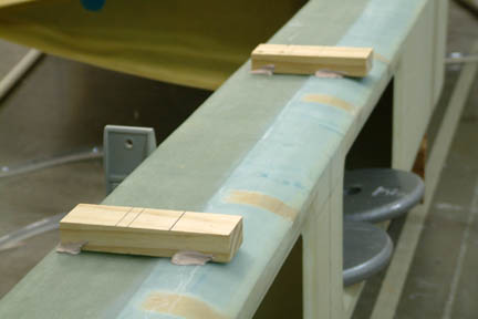 My
next step is to install the center section spar to the fuselage. Though the
center section spar is integrated to the main wing (leveled), I doubted I'll
mounting the center section spar to the fuselage with the wings attached. I
decided to add a couple small level boards onto the center section spar at this
time such that they have the independent level indicators (as the wings). As
shown, these two level boards allows me to level the center section spar fore
& aft and side to side. My
next step is to install the center section spar to the fuselage. Though the
center section spar is integrated to the main wing (leveled), I doubted I'll
mounting the center section spar to the fuselage with the wings attached. I
decided to add a couple small level boards onto the center section spar at this
time such that they have the independent level indicators (as the wings). As
shown, these two level boards allows me to level the center section spar fore
& aft and side to side.
[Hindsight]
These level boards proved to be useful again when I mount my upper firewall in
Chapter 18 - Section 7.
|
Now,
back to Chapter 14 - Section 10 - Installing the spar onto the fuselage ...
...