Chapter
21 - Section 4
Vent,
Screen and Drain
Routing
the Vent Lines
 The
plan's vent line configuration is pretty straight forward. However, as time
progresses, builders have made a few modifications to the venting configurations -
for better venting. Initially, I routed my vent lines along the edges of the
bulkheads under the T-Hats but decided against it because of the sharp bend
around the corners. It looks nice and neat while the top skin is off though... The
plan's vent line configuration is pretty straight forward. However, as time
progresses, builders have made a few modifications to the venting configurations -
for better venting. Initially, I routed my vent lines along the edges of the
bulkheads under the T-Hats but decided against it because of the sharp bend
around the corners. It looks nice and neat while the top skin is off though...
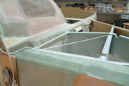
I
ended up following the plans method but added three small vertical holes through
the vent line as it exits the fuel tank (rear corner where the fuselage and
center section spar meet). I also added a couple of vertical holes at the open
end of the vent line as well. I made sure that all the vent holes were under the
T-Hats so that no flox would drip over them when I closed the top skin.
|
|
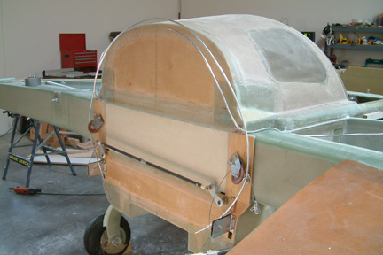 After
the vent lines exit the fuel tank, they are routed over the top of the turtleback and back down below the strake on the opposite side. My vent lines are at
the aft side of the firewall. After
the vent lines exit the fuel tank, they are routed over the top of the turtleback and back down below the strake on the opposite side. My vent lines are at
the aft side of the firewall.
|
Fuel
Return Line for Fuel Injection Engines
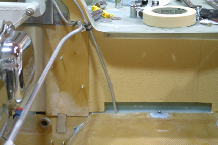
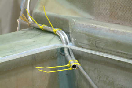 At
this time, I have not looked into the type of engine for my Cozy. I was told that
some fuel injection engines do not require any return lines - but they are
limited (I could be really wrong here, because I do not know much about aircraft
engines). I was recommended to put one in just in case. After much pondering, I
decided to add a fuel return to my right tank. I will certainly look for a fuel
injection engine that does not need a return line. The yellow ties are temporary.
I eventually floxed them in place. At
this time, I have not looked into the type of engine for my Cozy. I was told that
some fuel injection engines do not require any return lines - but they are
limited (I could be really wrong here, because I do not know much about aircraft
engines). I was recommended to put one in just in case. After much pondering, I
decided to add a fuel return to my right tank. I will certainly look for a fuel
injection engine that does not need a return line. The yellow ties are temporary.
I eventually floxed them in place.
|
|
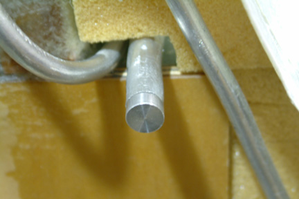 [Hindsight]
I eventually ordered my engine with fuel injection that does not require a
return line. Though I can remove it at this time, I decided to plug it at the
firewall. I made a small plug with my lathe. I eventually will seal it with flox
or something. [Hindsight]
I eventually ordered my engine with fuel injection that does not require a
return line. Though I can remove it at this time, I decided to plug it at the
firewall. I made a small plug with my lathe. I eventually will seal it with flox
or something.
|
Fuel
Drain Hole
 I
was rushing through the top and bottom skin and I missed the instruction for
cutting the hole for the fuel drain in the bottom skin. Fortunately I noticed it from reading
other builder's web sites. Since the location of the fuel drain is not very specific in the plan,
I figure as along as it sits over the sump blister, it should be OK.
None-the-less, I centered my fuel drain hole at 4 1/4" forward of the center
section spar face and 1 7/16" from the side of the fuselage. That puts my
fuel drain hole right at the center of the sump blister - to be built later. As I
mentioned, I missed carving a hole in the foam after I have glassed the upper
face of the bottom skin, I have to cut out the glass first, then the foam. I
have one of those circular cutter blades (shown) that I used to lance the glass
layer. Then I used a 1 1/4" hole saw and drilled out the drain hole. I dug
out the remaining glass ring with a blade. Finished the hole with a dowel and
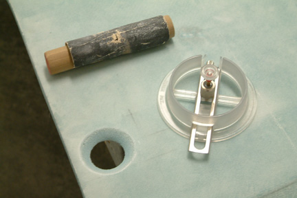
sand paper. I
was rushing through the top and bottom skin and I missed the instruction for
cutting the hole for the fuel drain in the bottom skin. Fortunately I noticed it from reading
other builder's web sites. Since the location of the fuel drain is not very specific in the plan,
I figure as along as it sits over the sump blister, it should be OK.
None-the-less, I centered my fuel drain hole at 4 1/4" forward of the center
section spar face and 1 7/16" from the side of the fuselage. That puts my
fuel drain hole right at the center of the sump blister - to be built later. As I
mentioned, I missed carving a hole in the foam after I have glassed the upper
face of the bottom skin, I have to cut out the glass first, then the foam. I
have one of those circular cutter blades (shown) that I used to lance the glass
layer. Then I used a 1 1/4" hole saw and drilled out the drain hole. I dug
out the remaining glass ring with a blade. Finished the hole with a dowel and
sand paper.
|
Fuel
Strainer
 I
bought my fuel strainer from ACE hardware store as many builders did before me.
It was a bit big but workable. The fuel strainer flange butts against the
fuselage sides and will not sit perfectly centered to the fuel drain hole. My
opportunity came when I went by an Asian supermarket (you have to live in Los
Angeles to find one of those). I found a smaller tea strainer - just a hair larger
than the fuel drain hole. You have to look at the fine print and in Chinese
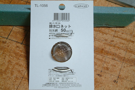
that says "high quality stainless steel" I
bought my fuel strainer from ACE hardware store as many builders did before me.
It was a bit big but workable. The fuel strainer flange butts against the
fuselage sides and will not sit perfectly centered to the fuel drain hole. My
opportunity came when I went by an Asian supermarket (you have to live in Los
Angeles to find one of those). I found a smaller tea strainer - just a hair larger
than the fuel drain hole. You have to look at the fine print and in Chinese
that says "high quality stainless steel"  . .
|
|
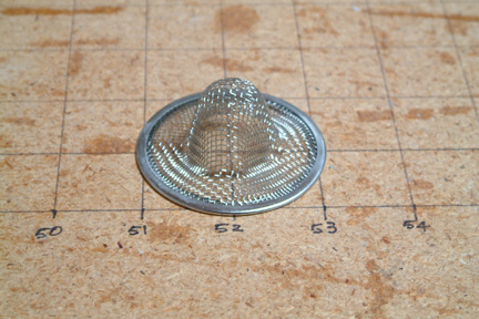 Here's
the picture of the strainer on a scale. As shown, its a hair larger than 2"
in diameter and it will fit over the fuel drain perfectly. Here's
the picture of the strainer on a scale. As shown, its a hair larger than 2"
in diameter and it will fit over the fuel drain perfectly.
[Hindsight]
I installed this fuel strainer at the fuel inlet pipe instead of the Plan's
location. The installation is discussion in Section 4.
|
Fuel
Drain at Sump
With
the concerns (discussed above), I decided to add a second fuel drain at the
lowest point of the sump. I expect this fuel drain to catch most of the water
(in the fuel). I made up a hard point and ordered a 1/4" NPT (instead of
the 1/8") fuel drain for the purpose. The reason for the larger fuel drain
is that, in the event I need to clean out any larger debris in the sump, I will have a
least a small opening / access (~1/2") into the fuel sump. I can stick
a small vacuum tube for debris extraction.
Screen
Location
 According
to the Plan, a dome shape screen is to be secured over the fuel drain hole to the sump. This
screen is to block out larger debris away from the fuel inlet lines (located in
the sump). The problem is that the location of the screen is far from the fuel
cap and its almost impossible to get to (for cleaning), once the fuel tank is
sealed. You may
be able to see the larger debris around the dome shape screen, but you may be
powerless to get to (to clean it out). I am just not too kin about this set up
though no one had any problem with it... According
to the Plan, a dome shape screen is to be secured over the fuel drain hole to the sump. This
screen is to block out larger debris away from the fuel inlet lines (located in
the sump). The problem is that the location of the screen is far from the fuel
cap and its almost impossible to get to (for cleaning), once the fuel tank is
sealed. You may
be able to see the larger debris around the dome shape screen, but you may be
powerless to get to (to clean it out). I am just not too kin about this set up
though no one had any problem with it...
Since
my second fuel drain provides a ~1/2" access hole at the sump, I decided to
move my screen right over the fuel outlet piping instead of the fuel drain hole at
the strake (Plan's location). Therefore, if there is any debris or water in the
fuel tank, they will eventually go into the sump. My fuel line will be protected
by the screen while I can drain or remove debris / water out of the fuel drain
access at the sump.
|
|
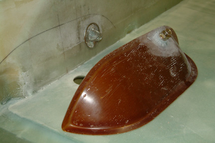
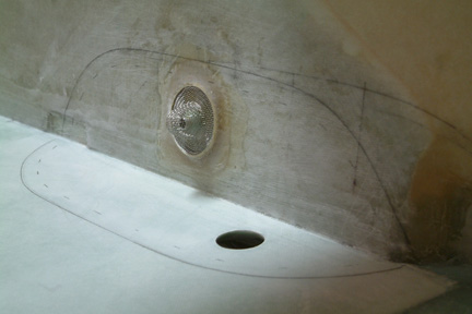 Here's
a picture of my dome shaped screen floxed and glassed in place over my fuel line. It's the same concept as the fuel line strainer that are commonly
used by other aircraft designs. Note the plane is on its upside down position. Here's
a picture of my dome shaped screen floxed and glassed in place over my fuel line. It's the same concept as the fuel line strainer that are commonly
used by other aircraft designs. Note the plane is on its upside down position.
|
Fuel
Drain at Leading Edge
The
Feather Lite leading edge does not have a 'front fence TLE' to herd any water
condensation to the fuel drain. It would be very difficult to 'catch' the water
condensation with this fuel drain. My bigger concern is that - what if the water
went down to the sump? I will never be able to get them out. After much consideration, I decided to
add a second fuel drain at the low point of the fuel sump. I followed the plans instructions for mounting
the fuel drain at the wing's leading edge.
|
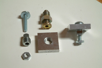 A
builder experienced a leak at this exact location. In
order to safeguard this from happening, I decided to devise some way to squeeze
the hard point against the glass during cure. I
drilled a small hole through the 1/8" NPT plug (note the hole through the
silver color plug to the left of the picture) to allow a small bolt to go
through. Picture
(left) shows the 1"x1"x1/4" hard point, the 1/8" NPT plug
(with a drilled hole), a common bolt and nut and a fuel
drain. A
builder experienced a leak at this exact location. In
order to safeguard this from happening, I decided to devise some way to squeeze
the hard point against the glass during cure. I
drilled a small hole through the 1/8" NPT plug (note the hole through the
silver color plug to the left of the picture) to allow a small bolt to go
through. Picture
(left) shows the 1"x1"x1/4" hard point, the 1/8" NPT plug
(with a drilled hole), a common bolt and nut and a fuel
drain.
|
|
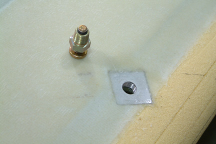
 Once the hard point is
buried in foam with flox, I slipped the small bolt through the 1/8" plug and hand
tightened the nut. This helped to bring the hard point tight against the
underlying glass, thus squeezing the flox nicely in between to cure. Once the hard point is
buried in foam with flox, I slipped the small bolt through the 1/8" plug and hand
tightened the nut. This helped to bring the hard point tight against the
underlying glass, thus squeezing the flox nicely in between to cure.
|
|
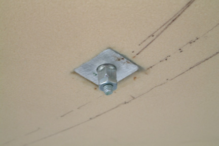
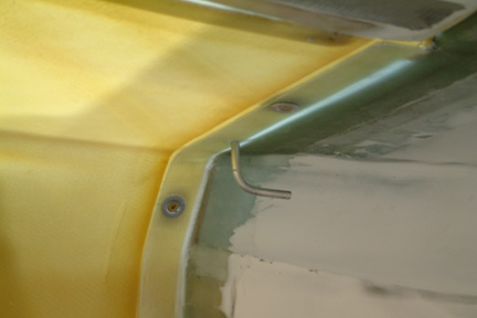
 Here's
a picture of my fuel drain at the leading edge. Here's
a picture of my fuel drain at the leading edge.
Note
that the fuselage is upside down for glassing the bottom skin. After the glass
cured, I clear out the threaded hole.
|
Fuel
Sight Gauge
I
did not install the fuel sight gauge until I know where the bottom of the fuel
tanks are. I learned that the 'window' I made in Chapter 5 were ~1/2" too
low. I have to trim the fuel sight gauges shorter to fit them in position such
that the drain holes will be situated at the bottom of the fuel tank. I also
epoxied the metal inserts onto the sight gauges to prevent them from plugging up
(per some Cozy fliers).
|
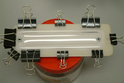 Here's
a picture on epoxying the viewing glass onto the white back plate. Here's
a picture on epoxying the viewing glass onto the white back plate.
|
|
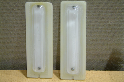 I
also made a 1 layer glass template around the viewing window of the sight gauge
such that I will have a more defined (cleaner) outline when it is glassed in
place. I have seen some pretty rough looking edges around the sight gauges at
some of the Cozy meets. I
also made a 1 layer glass template around the viewing window of the sight gauge
such that I will have a more defined (cleaner) outline when it is glassed in
place. I have seen some pretty rough looking edges around the sight gauges at
some of the Cozy meets.
You
can see the metal inserts as well as the BID template around the viewing window.
Since
the fuel sight gauge position is dependent on the lower drain hole relative to
the bottom of the fuel tank, I predrilled the bottom at the fuselage first. Then
I trimmed the fuel sight gauge to fit inside the fuselage cavity. The space is
tight but it worked out OK for me. Then I microed the sight gauge in place and
glassed over the entire gauge with 2 layers of BID. The LED (supplied) was also
glassed in place at the same time.
|
Fuel
Probe
The
Princeton fuel probe is a popular added feature among Cozy builders. I decided
to add a set as well. I was not able to get any return phone call from Todd
after repeated calls. I ended up buying the Princeton Advance Probe from
Aircraft Spruce. I also requested an 18" long cable at the end of the probe
with no additional cost. As many builders, I cut the probes to length - 7
3/4", leaving 1/8" spacing between the tip of the probe and the bottom
of the fuel tank.
|
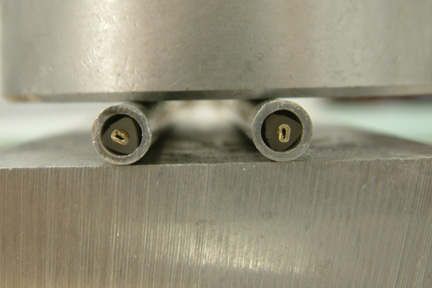 I
did not like cutting the probe with my Dremel (on my trial run) - quite a bit of
vibration and heat build up. I ended up cutting it off with my table top lathe -
resulting in a much cleaner cut with much less heat being generated. Make sure you
do not lose those 'mini' triangular spacers to keep the center probe from
touching the outside tube (housing). I learned from the Cozy forum to pinch the
inner OR the outer tube to keep the 'mini' triangular spacer from slipping out
in time. I chose the easy way by squeezing the inner tube with a pair of pointed
nose pliers. Note the inner tube ends are not round anymore. If you look close,
you can see the 'mini' triangular spacers hidden in the tube ends. I
did not like cutting the probe with my Dremel (on my trial run) - quite a bit of
vibration and heat build up. I ended up cutting it off with my table top lathe -
resulting in a much cleaner cut with much less heat being generated. Make sure you
do not lose those 'mini' triangular spacers to keep the center probe from
touching the outside tube (housing). I learned from the Cozy forum to pinch the
inner OR the outer tube to keep the 'mini' triangular spacer from slipping out
in time. I chose the easy way by squeezing the inner tube with a pair of pointed
nose pliers. Note the inner tube ends are not round anymore. If you look close,
you can see the 'mini' triangular spacers hidden in the tube ends.
|
Fuel
Probe Position
It
took me a while before deciding how and where to mount the fuel probes. I wanted
to mount the probes vertically down from the top skin and where the fuel level
is most stable. I was told it should be at FS103. The problem is that if I put
it so far forward, I may have a problem in hiding it under the fairing. I
decided to move it back a bit, actually right over the fuel drain hole and
3/8" from the side of the fuselage.
|
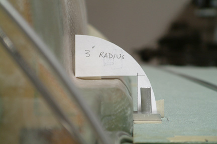 I
made a 1" square 1/4" thick aluminum hard point (with an 1/8" NPT)
for mounting the probes. To make sure I can hide the head of the probes
under the top fairings, I made a 3" and 4" paper template and held it
up against the canopy. Looks like I can hide it even with a 3" radius
fairing. I
made a 1" square 1/4" thick aluminum hard point (with an 1/8" NPT)
for mounting the probes. To make sure I can hide the head of the probes
under the top fairings, I made a 3" and 4" paper template and held it
up against the canopy. Looks like I can hide it even with a 3" radius
fairing.
|
Completing Vent Lines
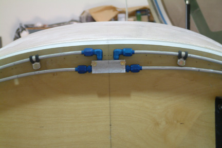 I
did not return to the vent lines until I started working on the firewall aft in
Chapter 23. There were many discussion in the Cozy Forum regarding the pros and
cons of the small holes at the back of the vent lines. I decided to leave them
the way it is. In addition, I added a center block (per Buly) to relieve the
tank pressure between the two tanks as well as potential siphoning effect. I
also anchored the vent lines with multiple hose clamps as shown. I
did not return to the vent lines until I started working on the firewall aft in
Chapter 23. There were many discussion in the Cozy Forum regarding the pros and
cons of the small holes at the back of the vent lines. I decided to leave them
the way it is. In addition, I added a center block (per Buly) to relieve the
tank pressure between the two tanks as well as potential siphoning effect. I
also anchored the vent lines with multiple hose clamps as shown.
|
|
 Here's
a picture showing the vent line exiting the cowling. I have to drill a 1/4" hole
through the strake lip for the vent line to exit. I also had to cut a small slot
on the cowling to accommodate the same. Here's
a picture showing the vent line exiting the cowling. I have to drill a 1/4" hole
through the strake lip for the vent line to exit. I also had to cut a small slot
on the cowling to accommodate the same.
|
|
 Here's
a picture showing the vent line outside the fuselage. Supposedly, the ram air
plays a small part in keeping the fuel from spilling out of the tank when it is
under pressure. Here's
a picture showing the vent line outside the fuselage. Supposedly, the ram air
plays a small part in keeping the fuel from spilling out of the tank when it is
under pressure.
|