Before laying out the panel, I must first decide what
instruments I need to support my Cozy mission. Well, I am not sure
![]() .
I plan to fly VFR most of the time, IFR only if I am in a jam, no night flying
(if I can avoid it) and certainly not in IMF conditions. In addition to planned
missions, I wanted to be able to get the instruments - cheap! I started looking
into Cozy flyers' IP and asked a lot of questions. After months of poking
around, I finally ended up with a list of instruments that I am comfortable
with.
.
I plan to fly VFR most of the time, IFR only if I am in a jam, no night flying
(if I can avoid it) and certainly not in IMF conditions. In addition to planned
missions, I wanted to be able to get the instruments - cheap! I started looking
into Cozy flyers' IP and asked a lot of questions. After months of poking
around, I finally ended up with a list of instruments that I am comfortable
with.
Panel Layout
|
Trial and Error with Paper IP
|
|
First Aluminum IP
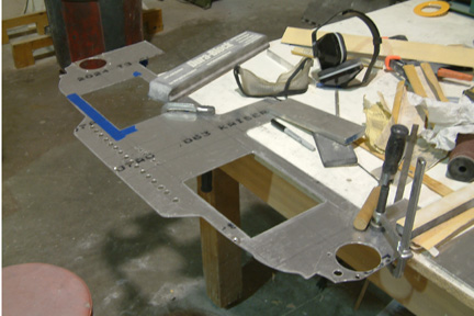
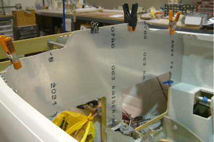
Here's a picture of my first aluminum IP. I used 2024 T3 0.063" thickness. It took considerable amount of trimming and sanding to get it to fit nicely without any interference to the IP cover. |
Here are a few more subsequent trimming and fitting of the aluminum panel onto the glass IP.
 |
 |
 |
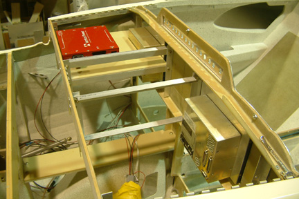 |
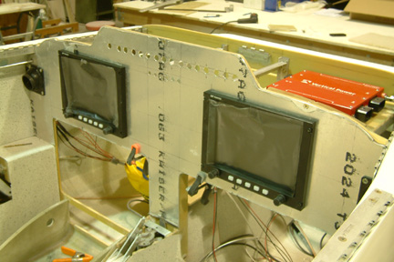
As shown above, I fitted my GRT HX EFIS to the aluminum panel. I bought the GRT EFIS used, but in really good shape and good price. It came with dual AHRS, and two (2) magnetometers. Note that I started to add angle aluminum (shelf support beams) between the IP and F28. It is because I need additional shelves to mount my Vertical Power (VPX Pro), Skyradar and the dual AHRS. At this time, I have not received my radio stack instruments. I ordered them from SteinAir for the Garmin GTN650, PS Engineering 8000BT, Trig Transponder TT31 and a back up Com radio Garmin 200.
|
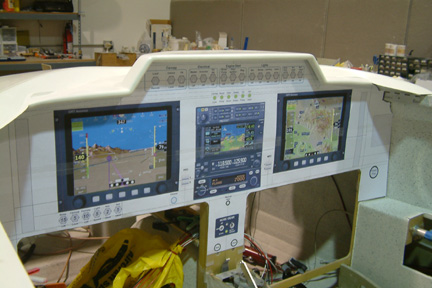
One of the requirement is that all instrument/switches
must be identified or labeled. Printed overlay can be so flexible and one can
put unlimited coloring and shading for enhancement. I plan to include a
picture of my control stick and it's switch labels on the panel because I heard
that it was difficult to print lettering onto my infinity stick grip. Note my
first trial with fading color on the overlay |
 There are many panel layout software available in the web.
Some panel makers even offer them for free to attract your business. I used a
graphics program (Corel Draw) for most of my work, so I decided to stick with
it. This graphics program has the layering capability, which, in my opinion, is
perfect for the task. For example, I like to put the outline of my instrument
panel (IP) in the outline layer, so that I can just print out the outline on
paper and trial fit it to my actual panel before cutting metal. One the other
hand, I put the cut outs (i.e. holes for toggle switches, instruments, dials,
etc.) on a different layer such that I can trace out the cutout positions onto
the fiber glass IP. I put the instrument images on the instrument layer such
that I can see how the layout looks like. Lastly, I made a construction line
layer such that I can place all the alignment marks for attaching the print out
to the actual IP precisely and consistently every time. The software
allows me to show (or print) each individual layer or a combination there of. Here's a picture of my IP outline and cut outs.
There are many panel layout software available in the web.
Some panel makers even offer them for free to attract your business. I used a
graphics program (Corel Draw) for most of my work, so I decided to stick with
it. This graphics program has the layering capability, which, in my opinion, is
perfect for the task. For example, I like to put the outline of my instrument
panel (IP) in the outline layer, so that I can just print out the outline on
paper and trial fit it to my actual panel before cutting metal. One the other
hand, I put the cut outs (i.e. holes for toggle switches, instruments, dials,
etc.) on a different layer such that I can trace out the cutout positions onto
the fiber glass IP. I put the instrument images on the instrument layer such
that I can see how the layout looks like. Lastly, I made a construction line
layer such that I can place all the alignment marks for attaching the print out
to the actual IP precisely and consistently every time. The software
allows me to show (or print) each individual layer or a combination there of. Here's a picture of my IP outline and cut outs.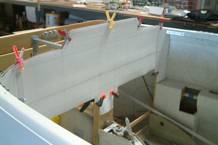
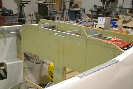
 Using the paper IP as a template, I was ready to make my
aluminum IP. Though I have seen some builders cut off the entire original fiber
glass panel and mount a thick aluminum IP in its place. I believe it is because
one has to remove so much of the glass panel behind the aluminum panel, its no
point in keeping it. The drawback, is that they must build some kind of
structure to prop it up. I chose to leave the glass panel in place and cut a whole
bunch of holes as needed. I think in a long run, its less time consuming, and
above all, I am maintaining the Original structure in tack - almost anyway!
Using the paper IP as a template, I was ready to make my
aluminum IP. Though I have seen some builders cut off the entire original fiber
glass panel and mount a thick aluminum IP in its place. I believe it is because
one has to remove so much of the glass panel behind the aluminum panel, its no
point in keeping it. The drawback, is that they must build some kind of
structure to prop it up. I chose to leave the glass panel in place and cut a whole
bunch of holes as needed. I think in a long run, its less time consuming, and
above all, I am maintaining the Original structure in tack - almost anyway! 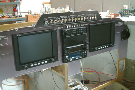 As
I was mounting the aluminum IP over the original glass IP, I have to put a few
counter sink screws through them. Regardless how careful I was, it just shows
the cut marks, nicks and scratches on the aluminum. I decided to try a printed overlay on top of
the aluminum IP. With the advancement of ink jet printing, one can print a
multi-color polycarbonate IP as an overlay. Since I have a ink jet color printer
at work, I printed out a temporary overlay on thick paper and try it out.
As
I was mounting the aluminum IP over the original glass IP, I have to put a few
counter sink screws through them. Regardless how careful I was, it just shows
the cut marks, nicks and scratches on the aluminum. I decided to try a printed overlay on top of
the aluminum IP. With the advancement of ink jet printing, one can print a
multi-color polycarbonate IP as an overlay. Since I have a ink jet color printer
at work, I printed out a temporary overlay on thick paper and try it out.