I ordered my radio stack instruments in late
December 2013
- time to start planning and fabricating the mounting structure and shelves for
them. There are many systems in the market that are flexible, but rather costly. I decided to fabricate them
myself instead
because I anticipated a high degree of customization and fitting in this process.
My radio stack consists of PS Engineering 8000BT, Garmin GTN650, Garmin GTR200
and Trig Transponder 31. I also ordered the harness for my radio stack from
Stein. All the instruments, harness and drawing arrived in mid January 2014. I
took detailed pictures at the back of the radios and the harness because I
anticipated the removal of these harness for ease of installation. I was glad I
did ![]() .
.
|
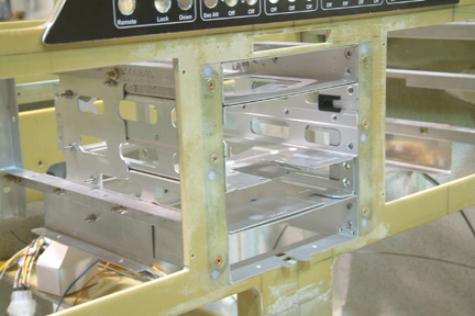
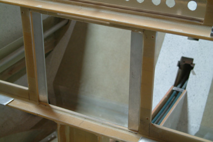
Here's a picture of the radio trays fitted to my radio frame structure. Note the side panel mounted against the horizontal rails? It will be trimmed some more after I have determined where the radio tray mounting holes and the venting holes are.
|
Unexpected Interference
|
|
Here's what I did...
I removed a strip of foam (~1 1/4") on both sides of the radio tray, leaving the front layer of glass in tact. The three screw holes were the left over holes and will be filled later on. |
|
|
|
|
|
|
|
|
|
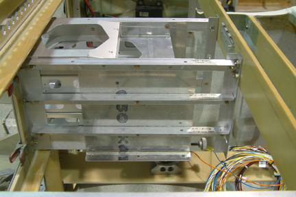
Final mounting of radio stack trays. Its a lot firmer and
secure |
 I
stacked the trays together and re-measure its width and height and found them to
be a bit taller than their respective drawings. It is because they have small
dimples above and below their radio trays - just to keep a slight separation
from their neighboring component. Once established, I re-marked and cut the radio stack hole onto my
Instrumental Panel.
I
stacked the trays together and re-measure its width and height and found them to
be a bit taller than their respective drawings. It is because they have small
dimples above and below their radio trays - just to keep a slight separation
from their neighboring component. Once established, I re-marked and cut the radio stack hole onto my
Instrumental Panel.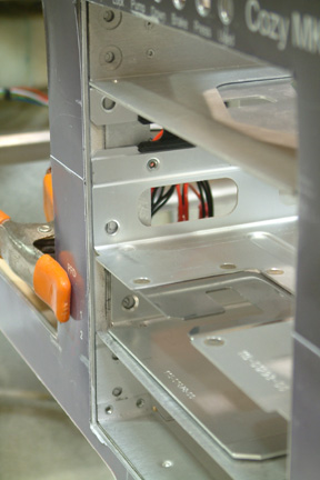 The
mounting holes for the radio trays are quite far forward to the IP, majority of
them lined up to the foam core of the original glass IP
The
mounting holes for the radio trays are quite far forward to the IP, majority of
them lined up to the foam core of the original glass IP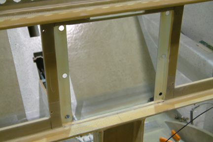
 Then
I epoxy an aluminum strip against the glass for strength and stiffness.
Then
I epoxy an aluminum strip against the glass for strength and stiffness.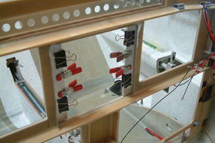 Then
I added a layer of BID over the aluminum strip and around the foam core, sealing
the edges.
Then
I added a layer of BID over the aluminum strip and around the foam core, sealing
the edges.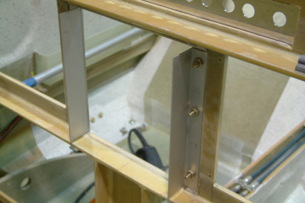 Add
a wider angle strip (1 1/2") for the radio tray.
Add
a wider angle strip (1 1/2") for the radio tray.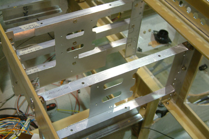 Radio
tray structure re-installed. Note the side panels are further drilled and
trimmed to match up with the radio tray holes from the manufacturers.
Radio
tray structure re-installed. Note the side panels are further drilled and
trimmed to match up with the radio tray holes from the manufacturers.