Chapter
22 - Section 3C
Auto Pilot Servos
My auto-pilot is part of the GRT Hx system. It does not
require an extra electronic instrumentation unit - saving Instrument Panel
space. The only hardware are the two servos that are driven and integrated to
the Hx system. When the GRT system arrived, the servos (pitch & roll) were
packaged in individual bags, together with a mounting bracket, rod ends,
extension rods, all accessory bolts and buts, and a wire harness connecting the
servos to the EFIS, and documentation.
Pitch Servo
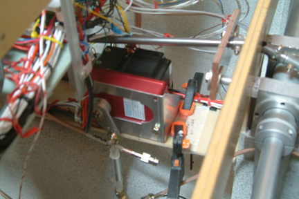 The
most convenience location for my pitch servo is on the bridge (I built earlier)
above the nose wheel well, right under the canard bell crank. You may have to
look closer for the beige color bridge (where the red/black servo) is being
clamped down. The aluminum mounting bracket is supplied by GRT with the servos. The
most convenience location for my pitch servo is on the bridge (I built earlier)
above the nose wheel well, right under the canard bell crank. You may have to
look closer for the beige color bridge (where the red/black servo) is being
clamped down. The aluminum mounting bracket is supplied by GRT with the servos.
|
Optimizing Pitch Servo Mounting Location and Length of
Extension Arm
 GRT
documentation provided clear guidance to prevent over-rotation of the servo arm
and mounting location for the auto-pilot to perform its duty without
obstruction. Most of us know, at this point of our building process, there is
limited space for doing all that - imagine placing the canard right over the
servo (as shown in the above picture). I have to find a more convenient setting
to figure all these out. It turned out to be pretty simple... GRT
documentation provided clear guidance to prevent over-rotation of the servo arm
and mounting location for the auto-pilot to perform its duty without
obstruction. Most of us know, at this point of our building process, there is
limited space for doing all that - imagine placing the canard right over the
servo (as shown in the above picture). I have to find a more convenient setting
to figure all these out. It turned out to be pretty simple...
I just tape down a couple of cardboard boxes and boards on
my work bench to simulate the height between the canard bell crank to the
bridge. Then I sat the canard on top of the card board boxes. I decided to
raised the pitch servo about 1" above the bridge surface to allow other wires to
route around and under it. Again, if you look close, you can see the 3/4"
U-extrusion where the servo mounting bracket is bolted to. By adhering to GRT's
mounting guidance/instructions, the length of the extension arm can be
determined. In my case, I have to shorten the extension arm supplied by GRT to
3.75" between rod end centers.
|
Here's my final mounting position and extension arm length
for my pitch servo:
- Height above support bridge (support U extrusion) = 3/4"
- Rod length between rod end centers = 3 3/4"
- Horizontal distance between bell crank center to Servo
crank center = 1 3/8"
- Angle between Servo Arm & Connecting rod end to bell crank
= 90 degrees
- Distance between forward edge of support bridge to front
of U extrusion = 2 3/26"
- Distance between bell crank Center line to front of U
extrusion = 2 3/16"
Just for my own record & documentation, an alternative Pitch Servo
location can be:
- Height above support bridge = 0"
- Rod length between rod end centers = 4 9/16"
- Horizontal distance between bell crank center to Servo
crank center = 1 3/8"
- Angle between Servo Arm & Connecting rod end to bell crank
= 90 degrees
|
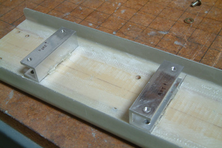 Since
there may be forces between the servo (pushing the bell crank) and the mounting
(bridge) surface, I decided to beef up the bridge a bit. In addition, the side
rails (walls) will be used for tie down and hiding the wire bundles running
along the bridge. Since
there may be forces between the servo (pushing the bell crank) and the mounting
(bridge) surface, I decided to beef up the bridge a bit. In addition, the side
rails (walls) will be used for tie down and hiding the wire bundles running
along the bridge.
|
Roll Servo
The roll servo is a bit simpler that the pitch servo, as
far as meeting the GRT mounting criteria. The difficult part was deciding were
to mount it. I had three possible locations:
- below and fore of the control stick grip, attaching to
the L-shaped bracket (originally made for the manual roll trim);
- behind the back of the pilot seat;
- by the hell hole.
I decided to mount it on top of the main gear bulk head
(bulk head with 2 large holes over the main gear) because of ample
space to mount the servo. Unfortunately, the right mounting bracket leg
(supplied by GRT) hangs over the big holes,
preventing a solid footing. Therefore, I have to come up with a different
mounting scheme...
|
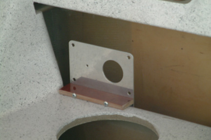
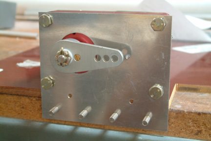 As
show (left) I made a flat aluminum plate with 4 mounting holes and a large
center hole to accommodate the servo. In addition, I added 4 tab bond holes at
the lower part of the mounting plate. The 4 tab bonds were floxed and glassed to
the aft face of the main gear bulkhead. To support the servo, I added a 1/4"
thick Phenolic block and bolt it to the mounting plate as well (note the two
lower holes). As
show (left) I made a flat aluminum plate with 4 mounting holes and a large
center hole to accommodate the servo. In addition, I added 4 tab bond holes at
the lower part of the mounting plate. The 4 tab bonds were floxed and glassed to
the aft face of the main gear bulkhead. To support the servo, I added a 1/4"
thick Phenolic block and bolt it to the mounting plate as well (note the two
lower holes).
|
|
 Here's
another picture on the mounting location of the Servo. Here's
another picture on the mounting location of the Servo.
|
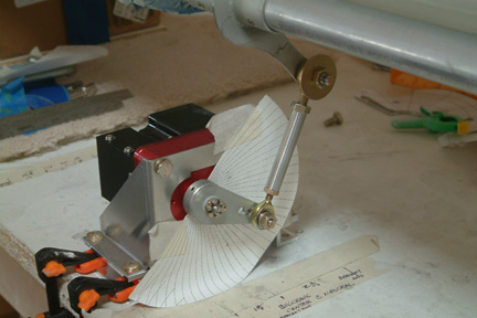
Connecting the Roll Servo Arm
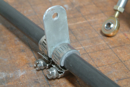 I
made a rod end mounting arm, sandwiched by 4 layers of glass on both sides, and
a conforming footing to the torque tube (as shown). After lining up with the
servo arm, I secure the rod end bracket to the torque tube with 2 pipe clamps.
This attachment method was used by the GRT servo mounting instructions as well. I
made a rod end mounting arm, sandwiched by 4 layers of glass on both sides, and
a conforming footing to the torque tube (as shown). After lining up with the
servo arm, I secure the rod end bracket to the torque tube with 2 pipe clamps.
This attachment method was used by the GRT servo mounting instructions as well.
Resultant rod length between rod end centers = 7". Center
rod (without rod ends) = 5.5"
|
Realigning control torque tubes
After both auto-pilot servos, roll trim and pitch trim are
mounted, I re-adjusted the torque tube lengths so that the the ailerons (left
and right) are moving in sync with each other as performed in Chapter 19 Section
11. The following is my new data:
| |
Stop Pin at: |
Left Digital Level
Reading |
Clearance Between
Left Stick Grip to Fuselage |
Right Digital Level
Reading |
Clearance Between
Right Stick Grip to Fuselage |
| Neutral |
Pilot |
12.1 |
>2.75" |
12.2 |
>2.75 |
| Neutral |
Co-pilot |
12.2 |
>2.75 |
12.3 |
>2.75 |
| Max Left Bank |
Pilot |
32.2 |
.25" |
6.0 |
.25" |
| Max Right Bank |
Co-pilot |
6.0 |
.25" |
32.1 |
.25" |