Battery Cover
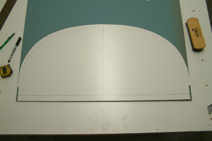 The
exact size and curvature of the battery cover took a bit of effort to determine.
Since the location of the cover is a bit forward of the firewall, it
will be a bit larger than the firewall. However, I can use the firewall
dimension as a rough guide. Fortunately, I still have the wood template
of the firewall from Chapter 6, therefore, I traced out the top edge of the
firewall onto a thin white board (shown left). If you look close, I made a
series of marks (at 1" intervals) radiating from the bottom of the center line
to the top edge of the board. I cut out the template for the next step. I
also added an extra 1" at the bottom for temporary clamping
onto the center section spar.
The
exact size and curvature of the battery cover took a bit of effort to determine.
Since the location of the cover is a bit forward of the firewall, it
will be a bit larger than the firewall. However, I can use the firewall
dimension as a rough guide. Fortunately, I still have the wood template
of the firewall from Chapter 6, therefore, I traced out the top edge of the
firewall onto a thin white board (shown left). If you look close, I made a
series of marks (at 1" intervals) radiating from the bottom of the center line
to the top edge of the board. I cut out the template for the next step. I
also added an extra 1" at the bottom for temporary clamping
onto the center section spar.
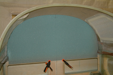 I
clamped the white board (template) onto the openings of the center section spar. With a
ruler aligned along the radiating line, I measured the width of the gap between
the roof of the turtle back and the top edge of the template. I took 20
measurements on each side, totaling 40.
I
clamped the white board (template) onto the openings of the center section spar. With a
ruler aligned along the radiating line, I measured the width of the gap between
the roof of the turtle back and the top edge of the template. I took 20
measurements on each side, totaling 40.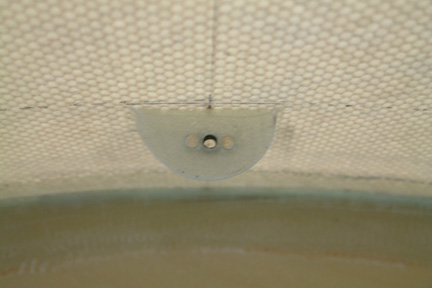 After
the trial fit, I drew out a half moon shaped paper template (2" width x 1"
height) and traced its outline on all 4 tabs. A bit of trimming and sanding made
it reasonably pleasing. The picture shows the tab at the top of the turtle back.
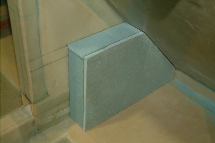
After
the trial fit, I drew out a half moon shaped paper template (2" width x 1"
height) and traced its outline on all 4 tabs. A bit of trimming and sanding made
it reasonably pleasing. The picture shows the tab at the top of the turtle back.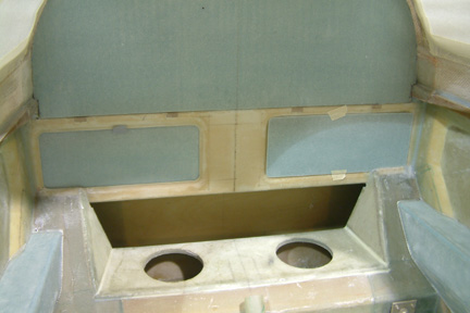 I
was not able to find any instruction in the Plans for the 'loud speaker covers'.
So I used the remaining 1/8" foam and made two covers to fit. Sanding down the
covers to fit took a lot more effort than
expected. Because of the uneven bevel edges of the speaker holes,
I had a
tough time making the covers to sit flush. After 2 1/2 hours of
sanding...fitting...sanding...fitting - they still looked ugly!
I
was not able to find any instruction in the Plans for the 'loud speaker covers'.
So I used the remaining 1/8" foam and made two covers to fit. Sanding down the
covers to fit took a lot more effort than
expected. Because of the uneven bevel edges of the speaker holes,
I had a
tough time making the covers to sit flush. After 2 1/2 hours of
sanding...fitting...sanding...fitting - they still looked ugly!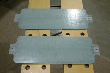 Since
I messed up the right cover, I ended up making a new cover set. At the far ends
of the cover, I embedded a 1" x 1" x 1/8" hard point. Then I
drilled and tapped the hard points. I drilled the 4 holes to accommodate the AN3
bolts at the longitudinal center of the covers,
1/2" from the opening edges. After I tightened the AN3 bolts to the hard
points, I traced out the opening onto the cover, then removed and trimmed to
shape. Here's a picture of my covers.
Since
I messed up the right cover, I ended up making a new cover set. At the far ends
of the cover, I embedded a 1" x 1" x 1/8" hard point. Then I
drilled and tapped the hard points. I drilled the 4 holes to accommodate the AN3
bolts at the longitudinal center of the covers,
1/2" from the opening edges. After I tightened the AN3 bolts to the hard
points, I traced out the opening onto the cover, then removed and trimmed to
shape. Here's a picture of my covers.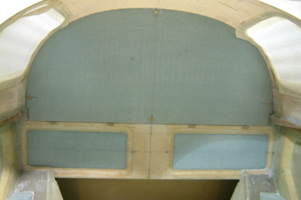
 The
landing brake cover consists of 3 sides. Instead of making a
mold out of 1"
foam (per Plan), I used a few pieces of left over foam from the strakes and made
a mock up cover. I have yet to round off the edges before glassing.
The
landing brake cover consists of 3 sides. Instead of making a
mold out of 1"
foam (per Plan), I used a few pieces of left over foam from the strakes and made
a mock up cover. I have yet to round off the edges before glassing.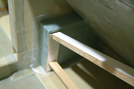 I
carefully sat the brake cover (with 2 layers of BID) back over the landing
brake and wetted out the overhung glass - which is now laying over the packing
tape. I used a couple of sticks to keep the landing brake cover tight against
the fuselage and let it cure over night.
I
carefully sat the brake cover (with 2 layers of BID) back over the landing
brake and wetted out the overhung glass - which is now laying over the packing
tape. I used a couple of sticks to keep the landing brake cover tight against
the fuselage and let it cure over night. 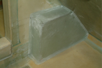 After
curing, I popped the cover off the mock up, trimmed, did a bit of sanding and held
it in place with 4 metal
screws per Plan. I may trim the edges down some more later on...
After
curing, I popped the cover off the mock up, trimmed, did a bit of sanding and held
it in place with 4 metal
screws per Plan. I may trim the edges down some more later on...