Chapter
13 - Section 11
Nose
Door
Reinforcing
the Glass Strut
Fabricating
NG-30
Installing
Worm Drive Assembly
Box
Assembly
Nose
Floor & Sides
Rudder
Pedals Master
Brake Cylinders
Completing
Nose Gear
Pitot
& Static System
Closing
the Top Nose
Door
|
 I
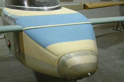
delayed working on this section until it I reached Chapter 18 (canopy) because I
wanted to shape the nose cover, the canard cover and canopy deck all at the same
time such that I get a smooth profile from nose tip to canopy. Shaping of the above
covers is detailed in chapter 18 section 11. Once shaped, I return back to this
section to document the nose cover build. I
delayed working on this section until it I reached Chapter 18 (canopy) because I
wanted to shape the nose cover, the canard cover and canopy deck all at the same
time such that I get a smooth profile from nose tip to canopy. Shaping of the above
covers is detailed in chapter 18 section 11. Once shaped, I return back to this
section to document the nose cover build.
|
Hinge
or No-Hinge
The
first decision I have to make regarding the nose door was its attachment method.
Many builders used the hinge method and some uses the plan (screw / flap
method). I
felt there are pros and cons in both methods.
As
for the hinge method, the plane will look cleaner with no screws and it will
provide a slight level of security from break-ins. I talked to several senior builders
and even received hinge pattern from Jon Dembs - Thanks Jon. However, I was
concerned about getting a nice fit because the shape of the 'J-hook' and its
mounting method has a lot to
do with it. I have heard multiple builders having difficulty in keeping their
seams tight and even in all sides. I also do not like the door hanging in the
way while I try to work inside the nose area. Most importantly, I am not sure
just the hinge and a locking mechanism (at the top side) will provide a good
seal (water and cold air) for the nose door.
The
screw method would be an easier installation and I think I'll have a much better
chance of getting the door nice and flush to the nose cover - which is important
to the appearance of the plane. In addition, I should be able to get a tight
seal from any leak as well. One of the argument regarding security is that
people will break in no matter what. But with the screw method, at least they
won't rip you door open to get at you GPS antenna - its a tough call as always. After
several days of pondering till I got over my mental indigestion ... I
finally decided to go the screw methods... hope I won't
regret my decision.
... I
finally decided to go the screw methods... hope I won't
regret my decision.
I
learned (from earlier Chapters) that deviating from plans methods always takes
longer. On the other hand, I just wasn't comfortable with the plan's method on holding down the nose door
with 2 screws and the canard cover lip. In addition, I am not certain I have the
necessary skill to carve a depression on the foam such that the nose door can sit
perfectly flush with the nose cover throughout (per plan). I decided to employ one of the techniques I
used in Chapter 13 section 5 - my removable landing light shield. Here's what I did...
| Making
the Nose Cover |
|
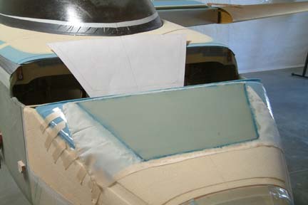 This
step pretty much follows the plans method. I first made a paper template of the
nose door - just to give me an idea how big the door is and how well it fits. I
did not use the door dimension per plan - I made it bigger instead. I projected
the sides of my nose cover door from the edges of the nose door
(at the tip of the nose). Then I drawn the outline
of the door on the nose cover foam. I cover the foam with
packing tape and lay up 3 plies of BID over the area. Peel plied and allowed to cure
overnight. Once cured, I carefully marked the location of the 'door' to the
center line of the fuselage as well as other markings to make sure I can put the
door back at the exact location later - this is important! Then I
removed the door and set aside for later use. This
step pretty much follows the plans method. I first made a paper template of the
nose door - just to give me an idea how big the door is and how well it fits. I
did not use the door dimension per plan - I made it bigger instead. I projected
the sides of my nose cover door from the edges of the nose door
(at the tip of the nose). Then I drawn the outline
of the door on the nose cover foam. I cover the foam with
packing tape and lay up 3 plies of BID over the area. Peel plied and allowed to cure
overnight. Once cured, I carefully marked the location of the 'door' to the
center line of the fuselage as well as other markings to make sure I can put the
door back at the exact location later - this is important! Then I
removed the door and set aside for later use.
|
| Glassing
the Nose |
|
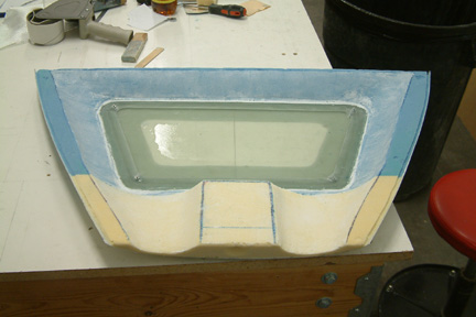
 This
is where I deviate from plan...instead
of carving a step/trench on the nose foam to accommodate the door, I glassed
(2 ply BID) and peel plied the entire nose cover as is. Once cured, I removed
the peel ply and re-traced an outline of the nose door on the top of the glass again (using the paper template). With my FEIN tool, long box cutter blades and circle
cutter, I cut
out the the door opening and push it out (as shown left). This
is where I deviate from plan...instead
of carving a step/trench on the nose foam to accommodate the door, I glassed
(2 ply BID) and peel plied the entire nose cover as is. Once cured, I removed
the peel ply and re-traced an outline of the nose door on the top of the glass again (using the paper template). With my FEIN tool, long box cutter blades and circle
cutter, I cut
out the the door opening and push it out (as shown left).
It
is important to note that the nose door corners are rounded. Therefore, it was difficult to make a perfectly smooth cut around the corners and at the
same time with a very narrow cut groove. If you look close at many Cozy nose
doors in the flight line, most of them have a wide seam and uneven widths... Since this is
the most 'looked' area, I wanted to do my best to impress ... ...
Even
with utmost care, the nose door I cut out has uneven corners and uneven seams -
but wait, I can do something about it! The cut out nose door & foam is
discarded. I
used my sanding stick, block, dowel etc. and clean off its edges of the cut out
hole - until I got a
nice, evenly shaped, clean opening.
|
|
 Now,
I laid the nose door (I made earlier) over the nice door opening - making sure it sat
exactly on the alignment marks. I tape the door down to the nose temporarily.
Using a fine tip Sharpie, I traced out the door opening onto the underside of
the nose door. Now,
I laid the nose door (I made earlier) over the nice door opening - making sure it sat
exactly on the alignment marks. I tape the door down to the nose temporarily.
Using a fine tip Sharpie, I traced out the door opening onto the underside of
the nose door.
|
|
 Then
I trim the nose door to the Sharpie outline - which will fit EXACTLY to the nose
door opening, with perfectly rounded corners and no seam! The 2 duct tape
'handles' allows me to pick up the nose door during my fitting process because
the door fits the opening nicely, there is no lip or edge for me to grab on
to. Then
I trim the nose door to the Sharpie outline - which will fit EXACTLY to the nose
door opening, with perfectly rounded corners and no seam! The 2 duct tape
'handles' allows me to pick up the nose door during my fitting process because
the door fits the opening nicely, there is no lip or edge for me to grab on
to.
I
bondoed stir sticks to the door to keep it flush to the nose cover for the next step.
|
Cutting
Out the Nose Cover Block
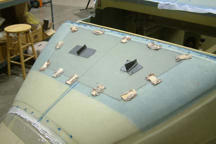
Before
cutting the nose cover block, I placed 3 markers on each side of the nose block
such that I can put them back on the exact location later on. Then I used my FEIN tool and cut along the sides. The
nose cover popped off easily since I was holding it down with only 3 dabs of 5
minute epoxy on each side.
| Stiffening
the Nose Door |
|
 Per
plan, my nose door was made out of 3 BID layers and is a bit flimsy. I
decided to beef it up a bit such that it can accommodate the counter sink hold
down screws. With the door bondoed flush to the cover (above) and the nose cover
cut away from the fuselage, I can flip the cover over. Per
plan, my nose door was made out of 3 BID layers and is a bit flimsy. I
decided to beef it up a bit such that it can accommodate the counter sink hold
down screws. With the door bondoed flush to the cover (above) and the nose cover
cut away from the fuselage, I can flip the cover over.
I
removed a .5" strip of foam (from the cover) around the door cover and sand it
down to the glass. I laid packing tape all around this newly exposed glass (around the
door). I made a 6 BID frame for the door, approximately 2"
wide, and glassed it in carefully, then peel plied.
After
cure, I removed all the bondoed sticks and pop the door back out - just to make sure I did not accidentally glass
the door to the nose cover ...This time I learned, I
heated up the bondo with a hair dryer before removing them - much easier. ...This time I learned, I
heated up the bondo with a hair dryer before removing them - much easier.
|
| Glassing
In The Support Flange |
|
 I
wrapped the edges of the door with packing tape and fit it back in place (with
slight force fit). I kept
the door flush with the nose surface using stir stick and hot glue this time
(instead of bondo). It worked
just as well (as bondo), except its easier to apply and cures quicker...and
probably much easier to remove later on. I
wrapped the edges of the door with packing tape and fit it back in place (with
slight force fit). I kept
the door flush with the nose surface using stir stick and hot glue this time
(instead of bondo). It worked
just as well (as bondo), except its easier to apply and cures quicker...and
probably much easier to remove later on.
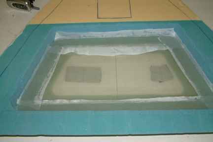
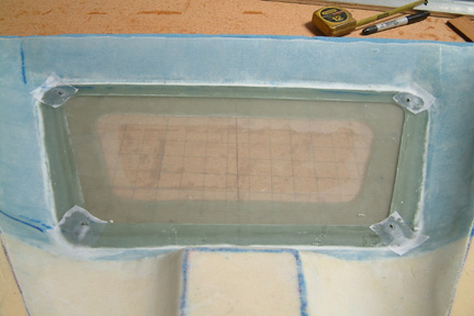
Prior
to glassing, I added a flox fillet along the added thickness of the door. I
made a 3 BID frame (~1.75" wide) and glassed it from the exposed edge of
the cover (around the frame) and over the door frame - creating a support
flange. While wet, I added strips of BID (7 layers) on top of the initial 3
BID frame - totaling 10 layers. The reason for so many layers such that I can
make a groove to bury a o-ring cord stock seal later on.
|
|
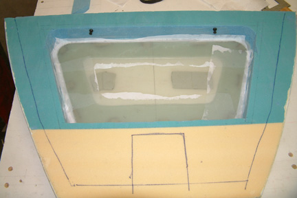
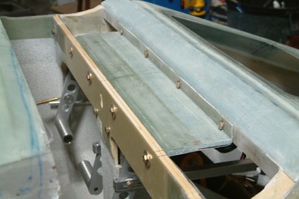
Here's a picture of the support flange. I has yet to be trimmed
it to the correct width. The door fits well - perfectly flush and no gap in all
sides . .
|
| Carving
The Cover Underside |
|
 The
joining location of my nose cover to the side of the fuselage is a bit different
than shown in the plans (Fig. 65). Therefore, I just have to be a bit creative
in interpreting what is required in carving the bottom sides of the cover.
Here's what I ended up with...If you look close, I have already trimmed the
support flange to .75" width. I have also microed the foam ready for
glassing. One location I wasn't sure about is at the opening between F0 and F5.
It needs to be protected because it will be exposed to weather elements - yet I
have no way of sealing it unless I take the nose wheel strut off...what a pain.
I decided to glass over the whole thing first and remember to seal it off when
opportunity arises. The
joining location of my nose cover to the side of the fuselage is a bit different
than shown in the plans (Fig. 65). Therefore, I just have to be a bit creative
in interpreting what is required in carving the bottom sides of the cover.
Here's what I ended up with...If you look close, I have already trimmed the
support flange to .75" width. I have also microed the foam ready for
glassing. One location I wasn't sure about is at the opening between F0 and F5.
It needs to be protected because it will be exposed to weather elements - yet I
have no way of sealing it unless I take the nose wheel strut off...what a pain.
I decided to glass over the whole thing first and remember to seal it off when
opportunity arises.
|
| Glassing
Under Side of Cover & Nut Plates |
|
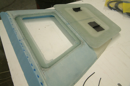
 Here's
a picture showing the underside of the cover after it had been glassed, peel plied and trimmed - 1
BID per plan. I also added 4 mounting screws that matches the ones used for the
forward nose cover. They are MS24694-S11 (8-32) stainless machine screws and
matching nut plates. Here's
a picture showing the underside of the cover after it had been glassed, peel plied and trimmed - 1
BID per plan. I also added 4 mounting screws that matches the ones used for the
forward nose cover. They are MS24694-S11 (8-32) stainless machine screws and
matching nut plates.
|
Tool
Compartment (not in Plans)
While
I had the nose cover cut out, I took the opportunity to install a tool
compartment (i.e. a set of
bulkhead) at the front of the nose as most builders. I set the bulkhead location
about 9" from F0 because it will give me a diagonal dimension of exactly 1
foot. Since I have already made room at the nose compartment for ballast, this
added compartment shall be used for storing necessary tools (see 2 pictures
below).
Painting
Inside the Nose
There
are many discussions in the archives regarding interior paints. Some suggested
Stone Flack (spray cans) and others Zalotone (HPLV spray paint) . I just wasn't
ready for the whole interior finishing and painting mode, I decided to go with
the Stone Flack spray paint even though most suggested that Stone Fleck will not
last as long as Zolatone. Matter of fact, some builders suggested no paint at
all because no one can see under the nose cover anyway - save some weight. I
know I won't be happy with bare glass and this is the best time to get it
covered up...
|
 I
first mask off all necessary areas and did a bit of pre-filling (dry micro). Got
a taste of what Chapter 25 (finishing) is all about. I think its gonna be one
tough chapter coming up I
first mask off all necessary areas and did a bit of pre-filling (dry micro). Got
a taste of what Chapter 25 (finishing) is all about. I think its gonna be one
tough chapter coming up ... Note
that small white spot on the floor? Feels like eternity to get a nice
contour. ... Note
that small white spot on the floor? Feels like eternity to get a nice
contour.
|
|
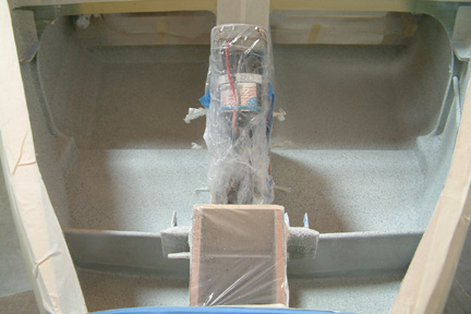 Shopping
of Stone Flack was a bit more effort than expected. I preferred lighter cover
for my interior and I eventually found them at the local fabric store (JoAnn's)
instead of Home Deport and Lowes. I used white primer (Plastic Kote), Soapstone
(Plastic Kote - Stone Flack) and Clear Coat (Krylone - UV resistance & non-yellowing). I
decided to use
a light coat of Stone Flack (just enough to camouflage the glass weaves) and the
white primer help to minimize Stone Flack coverage. Once completed, I sprayed 3
layers of Clear Coat. It turned out quite nice Shopping
of Stone Flack was a bit more effort than expected. I preferred lighter cover
for my interior and I eventually found them at the local fabric store (JoAnn's)
instead of Home Deport and Lowes. I used white primer (Plastic Kote), Soapstone
(Plastic Kote - Stone Flack) and Clear Coat (Krylone - UV resistance & non-yellowing). I
decided to use
a light coat of Stone Flack (just enough to camouflage the glass weaves) and the
white primer help to minimize Stone Flack coverage. Once completed, I sprayed 3
layers of Clear Coat. It turned out quite nice ...though
the picture is a bit small to see. ...though
the picture is a bit small to see.
|
| Glassing
the Nose Top |
|
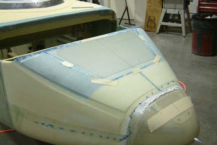
 Once
the interior paint cured, I place the nose cover back in place per my alignment
marks (I drawn 6 vertical line along the sides before I cutting the nose top
off). Then I mount the canard back in place and bolted it down. The reason for
mounting the canard is to make sure the nose will be glassed in position in
concert with the canard alignment pins and bolts. Once
the interior paint cured, I place the nose cover back in place per my alignment
marks (I drawn 6 vertical line along the sides before I cutting the nose top
off). Then I mount the canard back in place and bolted it down. The reason for
mounting the canard is to make sure the nose will be glassed in position in
concert with the canard alignment pins and bolts.
I
dug the trenches way too deep and I know I am going to have a lot to fill down
the road.
|
Torsional
Brace (Removable) - Not In Plans
This
is another one of those waterfall effects from deviating (from Plans) prior .
Instead of using the plans method for the rudder pedals, I change to the
Velocity design hanging type pedals. In addition, I re-design the Velocity
pedals (refer to Chapter 13 section 7) and mounted it a bit differently. Bottom
line is that I can only remove my rudder pedals by lifting it straight up.
.
Instead of using the plans method for the rudder pedals, I change to the
Velocity design hanging type pedals. In addition, I re-design the Velocity
pedals (refer to Chapter 13 section 7) and mounted it a bit differently. Bottom
line is that I can only remove my rudder pedals by lifting it straight up.
|
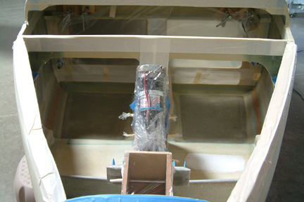
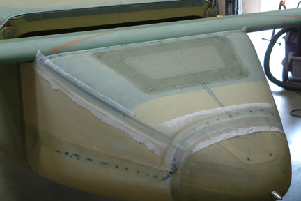
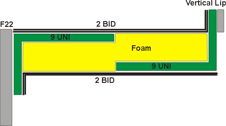 Here's
the challenge - the Plans torsional brace consists of a 3/8" foam piece with 1 ply of BID
connecting (glassed) F22 to the aft end of the nose cover. If I follow the Plans
approach, my rudder pedals will be entombed... Therefore, I need to build a removable
one - just incase. Picture (left) shows the general idea... Here's
the challenge - the Plans torsional brace consists of a 3/8" foam piece with 1 ply of BID
connecting (glassed) F22 to the aft end of the nose cover. If I follow the Plans
approach, my rudder pedals will be entombed... Therefore, I need to build a removable
one - just incase. Picture (left) shows the general idea...
|
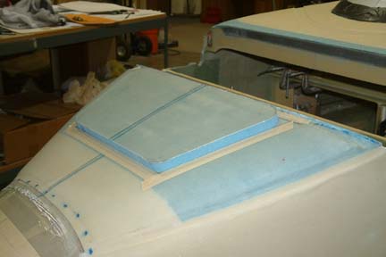
Vertical
Lip for Mounting the Removable Brace
First
I cut a strip of high density foam about 1.5" width x 29" long and
glassed it with 2 plies of BID per side. After it cures, I glassed it
to the aft end of the nose cover with 2 BID inside and outside forming a
vertical lip (gray).
|
 Next,
I build a set of glass angle strips (9 Ply UNI) as shown. Once cured, I cut it
in half down the center, lengthwise, forming 2 strips of glass angles (green). Next,
I build a set of glass angle strips (9 Ply UNI) as shown. Once cured, I cut it
in half down the center, lengthwise, forming 2 strips of glass angles (green).
|
|
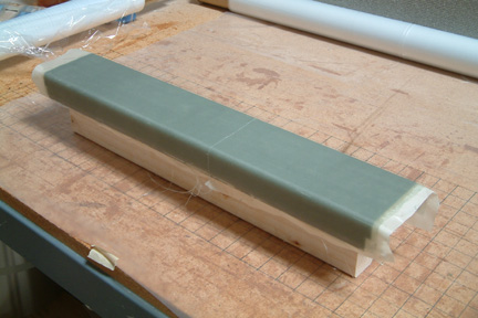
 I
measured and cut out a piece of 3/8" foam (yellow) with its width that fits snuggly
between F22 and the vertical lip. Then I sand a depression (lengthwise) on each
side of the foam to embed the glass angle strip I made (above). I
measured and cut out a piece of 3/8" foam (yellow) with its width that fits snuggly
between F22 and the vertical lip. Then I sand a depression (lengthwise) on each
side of the foam to embed the glass angle strip I made (above).
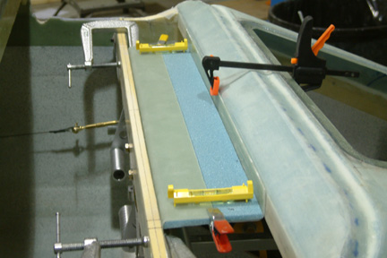
I
clamped the assembly in place (left) and laid 2 plies of BID on both top -
connecting the 2 angle strips together. Once cured, I flip the brace over and
glassed the bottom side with 2 BID - forming a strong & rigid brace that I
can bolt onto F20 and vertical lip. Note the 2 miniature (yellow) bubble levels
I used to keep the brace level during installation.
|
|
 Here's
a completed brace with 4 AN-3 bolts on each lip. I may install a set of nut
plates for it later on... Here's
a completed brace with 4 AN-3 bolts on each lip. I may install a set of nut
plates for it later on...
|
Things
To Do...
-
Seal off nose cover with BID tape from inside of F0, F5 and NG30.
-
Seal off nose door with o-ring chord stock, if necessary.