By
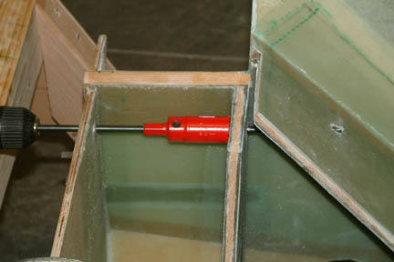
repeating the process above, the wire eventually will be taught, straight and
free. Using the final center positions as a guide, I took a long 1/4" drill
bit and drilled through the firewall and the bulkheads. I then pulled back the
long bit and added the 1" hole saw and put the two holes through the
bulkheads.
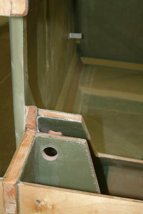
[Hindsight:
I received several private E-mail later pointing it out that the hole diameter
per plan is 1", but the drawing showed 3/4" and that the correct one
should be 3/4" per the drawing (M-10). With the torque tube being
9/16" in diameter, leaving 3/32" tolerance for each side. I am more
comfortable with a bit more tolerance because the torque tube coming long way
away. So, if I run into obstruction problems, I'll have the room for it. If not,
I'll slip a thin 1" OD PVC pipe inside the hole and make it
pretty.
I
was tempted to put the 1" hole in the firewall while I was at it, but
decided to double check. I am glad I checked, its not a 1" hoIe... I decided to leave it alone for now.
 In
this chapter, we will install the main landing gear and the landing brake. This
includes all the reinforcements to attach the main gear onto the fuselage, the
wheels, disc brakes, brake lines and brake fluid reservoir. The landing brake
(i.e. the big door under the belly) will be electric driven and this will be the
first moving part for this project. This is a long chapter and is divided into
several sections:
In
this chapter, we will install the main landing gear and the landing brake. This
includes all the reinforcements to attach the main gear onto the fuselage, the
wheels, disc brakes, brake lines and brake fluid reservoir. The landing brake
(i.e. the big door under the belly) will be electric driven and this will be the
first moving part for this project. This is a long chapter and is divided into
several sections: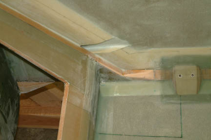 For
the forward bulkhead, 5 layers
of BID (2 different sizes) is required. This is one of the more
complicated surface profiles for glassing thus far. Anticipating the
challenge, I took time to prep the surfaces. That included grounding
down the doublers, rounding off the edges and floxing in corners. I also
tried various approaches including pre-cut cloth patterns (as suggested
by the plan), pre-wet the cloth, used different kinds of plastics - all
with little success in reducing the struggle. The wet cloth kept
stretching at the wrong places and wormed around instead of staying put
For
the forward bulkhead, 5 layers
of BID (2 different sizes) is required. This is one of the more
complicated surface profiles for glassing thus far. Anticipating the
challenge, I took time to prep the surfaces. That included grounding
down the doublers, rounding off the edges and floxing in corners. I also
tried various approaches including pre-cut cloth patterns (as suggested
by the plan), pre-wet the cloth, used different kinds of plastics - all
with little success in reducing the struggle. The wet cloth kept
stretching at the wrong places and wormed around instead of staying put 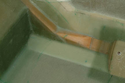 It
should be clear by now that there's only excess glass at three (3) locations for
trimming - along the fuselage floor and up the bulkhead wall; along the slope
edge of the bulkhead; and a small area around the wood seat belt anchor. I used
my Dritz scissors and trimmed the excess glass - JUST A BIT inside the
wetted edge at the fuselage bottom - the excess should still be dry but is held
together by that little bit of wetted glass you are trimming off. Trimming along
the bulkhead edges and around the wood anchor should be easy as we have done it
many times before. Once completed, I brushed down the unsettled edges, peel
plied
and let cure. I did not pre-cut any pattern or dart for the right side and it
took me approximately 1/2 the time to complete. Oh
yes, a bit of patience always helps
It
should be clear by now that there's only excess glass at three (3) locations for
trimming - along the fuselage floor and up the bulkhead wall; along the slope
edge of the bulkhead; and a small area around the wood seat belt anchor. I used
my Dritz scissors and trimmed the excess glass - JUST A BIT inside the
wetted edge at the fuselage bottom - the excess should still be dry but is held
together by that little bit of wetted glass you are trimming off. Trimming along
the bulkhead edges and around the wood anchor should be easy as we have done it
many times before. Once completed, I brushed down the unsettled edges, peel
plied
and let cure. I did not pre-cut any pattern or dart for the right side and it
took me approximately 1/2 the time to complete. Oh
yes, a bit of patience always helps 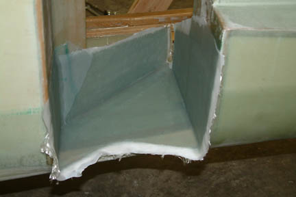 Since
I still have my fuselage on the rotisserie, I rotated it to its sides for this
operation. I did not make a pattern as suggested per plan. I just cut up three
triploid shaped BID (per plan dimension) and epoxied them down one at a time the
traditional way and peel plied. I trimmed the edges with scissors prior to
curing. Once
cured, I laid downed the remaining 2 plies of BID per plan. I did not have much
problem with these lay ups.
Since
I still have my fuselage on the rotisserie, I rotated it to its sides for this
operation. I did not make a pattern as suggested per plan. I just cut up three
triploid shaped BID (per plan dimension) and epoxied them down one at a time the
traditional way and peel plied. I trimmed the edges with scissors prior to
curing. Once
cured, I laid downed the remaining 2 plies of BID per plan. I did not have much
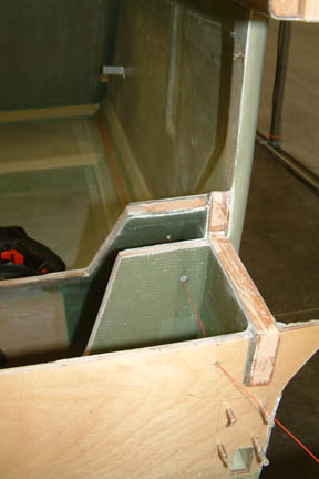
problem with these lay ups.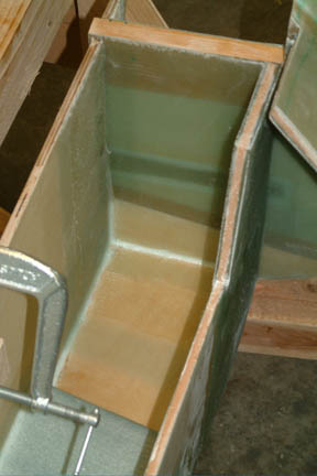 I
followed the plan method closely for this lay up. I rounded the outside corners
of the foam, sanded glassed area dull, vacuumed, microed the foam and radius the
inside corners with micro. Due to the tight space, I used a syringe to apply
micro onto the inside corners and smoothed them out with a shortened
& trimmed stir stick. I also shortened the brush handle for tugging the BID
into the corners.
I
followed the plan method closely for this lay up. I rounded the outside corners
of the foam, sanded glassed area dull, vacuumed, microed the foam and radius the
inside corners with micro. Due to the tight space, I used a syringe to apply
micro onto the inside corners and smoothed them out with a shortened
& trimmed stir stick. I also shortened the brush handle for tugging the BID
into the corners.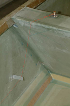 My eventual approach
to drilling these holes adheres to recommendations from the Cozy Girrrls and Wayne Hicks
(with minor deviations) as follows:
My eventual approach
to drilling these holes adheres to recommendations from the Cozy Girrrls and Wayne Hicks
(with minor deviations) as follows:
 I
took a 26 gauge wire (red) and thread it through all 4 holes, with one end tied to
the shoulder mount and the other to a weight (i.e. a c-clamp). The weight of
the c-clamp pulls the wire taught through the holes. As expected, the wire
zigzagged through the bulkhead holes. I marked the wire position (where it touches
hole walls). Pulled the wire back out of the hole and drilled a new 1/8"
hole at the newly marked location. Make sure you pull the wire out before
drilling otherwise the bit will grab the wire and make a siren like squeal
followed by a horrendous SNAP - all before you brain can say 'what the....'.
I
took a 26 gauge wire (red) and thread it through all 4 holes, with one end tied to
the shoulder mount and the other to a weight (i.e. a c-clamp). The weight of
the c-clamp pulls the wire taught through the holes. As expected, the wire
zigzagged through the bulkhead holes. I marked the wire position (where it touches
hole walls). Pulled the wire back out of the hole and drilled a new 1/8"
hole at the newly marked location. Make sure you pull the wire out before
drilling otherwise the bit will grab the wire and make a siren like squeal
followed by a horrendous SNAP - all before you brain can say 'what the....'.